Engine switching schemes for all modes. Motor control schemes
Hi all. The topic of today's article is the starting circuit of an asynchronous motor. As for me, this circuit is the simplest one that can be in electrical engineering. In this article, I have prepared two schemes for you. In the first picture there will be a circuit with a fuse to protect the control circuits, and in the second there will be no fuse. The difference between these circuits is that the fuse serves as additional element to protect the circuit from short circuit and as well as protection against spontaneous activation. For example, if you need to perform some work on the electric drive, then you disassemble the electrical circuit by turning off the machine and additionally you still need to remove the fuse and after that you can already start working.
Let's take a look at the first diagram. To enlarge the image, click on it.
 Figure 1. Starting an asynchronous electric motor with a squirrel-cage rotor.
QF - any circuit breaker.
KM - electromagnetic starter or contactor. I also designated the starter coil and the starter auxiliary contact with these letters in the picture.
SB1 is the stop button
SB2 - start button
KK - any thermal relay, as well as a thermal relay contact.
FU - fuse.
KK - thermal relay, thermal relay contacts.
M - asynchronous motor.
Now we will describe the process of starting the engine.
This whole circuit can be conditionally divided into power - this is what is on the left, and into the control circuit - this is what is on the right. To start with the whole electrical circuit you need to apply voltage by turning on the QF machine. And voltage is applied to the fixed contacts of the starter and to the control circuit. Next, we press the start button SB2, during this action, voltage is applied to the starter coil and it is drawn in and voltage is also applied to the stator windings and the electric motor starts to rotate. Simultaneously with the power contacts on the starter, the KM auxiliary contacts are closed through which voltage is applied to the starter coil and the SB2 button can be released. On this, the launch process is already over, as you can see for yourself, everything is very easy and simple.
 Figure 2. Starting an asynchronous motor. There is no fuse in the control circuit. To enlarge the image, click on it.
In order to stop the operation of the electric motor, just press the button SB1. By this action, we break the control circuit and the voltage supply to the starter coil stops, and the power contacts open and, as a result, the voltage on the stator windings disappears, and it stops. Stopping is as easy as starting.
That, in principle, is the whole scheme for starting an asynchronous motor. If the article helped you in some way, then share it on social media. networks, as well as subscribe to blog updates.
Sincerely, Semak Alexander!
The article considers the starting scheme of an asynchronous motor with a squirrel-cage rotor using non-reversing and reversing magnetic starters.
Squirrel-cage induction motors can be controlled using magnetic starters or contactors. When using low-power motors that do not require limitation of starting currents, the start is carried out by switching them on to the full voltage of the network. The simplest motor control circuit is shown in fig. one.
Rice. 1. Scheme of control of an asynchronous motor with a squirrel-cage rotor with a non-reversible magnetic starter
To start, the circuit breaker QF is turned on and thus the power circuit of the circuit and the control circuit are energized. When the SB1 “Start” button is pressed, the power circuit of the coil of the KM contactor is closed, as a result of which its main contacts in the power circuit are also closed, connecting the stator of the electric motor M to the mains. At the same time, the blocking contact KM is closed in the control circuit, which creates a power supply circuit for the KM coil (regardless of the position of the button contact). The motor is switched off by pressing the SB2 "Stop" button. In this case, the power supply circuit of the KM contactor is interrupted, which leads to the opening of all its contacts, the engine is disconnected from the network, after which it is necessary to turn off the QF circuit breaker.
The scheme provides the following types of protection:
From short circuits - using the QF circuit breaker and FU fuses;
from overloads of the electric motor - using thermal relays KK (opening contacts of these relays, when overloaded, open the power circuit of the KM contactor, thereby disconnecting the engine from the network);
zero protection - using the KM contactor (when the voltage drops or disappears, the KM contactor loses power, opening its contacts, and the engine is disconnected from the network).
To turn on the engine, you must again press the button SB1 "Start". If direct starting of the motor is not possible and it is necessary to limit the starting current of the asynchronous squirrel-cage motor apply undervoltage start. To do this, an active resistance or a reactor is included in the stator circuit, or a start through an autotransformer is used. 
Rice. 2 Scheme of control of an asynchronous motor with a squirrel-cage rotor with a reversible magnetic starter
On fig. 2 shows the control circuit of an asynchronous motor with a squirrel-cage rotor with a reversible magnetic starter. The circuit allows direct starting of an asynchronous squirrel-cage motor, as well as changing the direction of rotation of the motor, i.e. produce a reverse. The engine is started by turning on the QF circuit breaker and pressing the SB1 button, as a result of which the KM1 contactor receives power, closes its power contacts and the motor stator is connected to the network. To reverse the engine, press the SB3 button. This will turn off the KM1 contactor, after which the SB2 button is pressed and the KM2 contactor is turned on.
Thus, the motor is connected to the network with a change in the phase sequence, which leads to a change in the direction of its rotation. The circuit uses blocking from possible erroneous simultaneous activation of contactors KM2 and KM1 using break contacts KM2, KM1. The engine is disconnected from the network by the SB2 button and the QF circuit breaker. The circuit provides for all types of motor protection, considered in the control circuit of an asynchronous motor with a non-reversible magnetic starter.
MINISTRY OF EDUCATION OF UKRAINE
SEVASTOPOL HIGHER VOCATIONAL SCHOOL № 3
Graduation Written
EXAMINATION PAPER
"Installation of the electric motor control circuit"
Group 7/8 student:
Levitsky Pavel Vladimirovich
By profession:
ship electrician.
Supervisor:
E.I. Korshunova
Sevastopol.
1. Introduction. The role of electrical engineering in the development of shipbuilding
2 Main body
2.1 Motor control circuit
2.2 The main elements of the scheme and their purpose.
2.3 The principle of operation of the electrical circuit of the fan
2.4 Wiring technology
3. Materials used for mounting the circuit
4. Tools
5. Safety
Literature
1. Introduction. The role of electrical engineering in the development of shipbuilding
Electrical engineering in shipbuilding is of great importance. This branch of science and technology associated with the production, conversion and use of electrical energy.
Shipbuilding uses electrical and magnetic phenomena. Many kilometers of electrical wiring arteries are laid on ships, numerous electric drives of ship mechanisms are mounted, modern automatic devices, navigation and radio equipment are installed and adjusted.
The reliability and durability of the launched vessel depends on the reliability of electrical devices.
In 1832, Faraday discovered the law of electromagnetic induction and thus laid the foundation for electrical engineering. The year of birth of the ship's electric drive can rightfully be considered 1838, when the Russian scientist B.S. Yakobi created the world's first rowing electrical installation. The electric motor he made direct current was installed on a small boat and tested on the Neva. The engine was powered by a galvanic battery. A very weak energy base in the first half of the 19th century hampered the development of the electric drive, and electricity was used on ships only for lighting.
The first serious work on the formation of a ship's electric drive on Russian courts were undertaken in the second half of the 19th century. So in 1886 on the cruisers "Admiral Nakhimov", "Admiral Kornilov", "Lieutenant Ilyin" electric fans were used, and in 1892 on the armored cruiser "Twelve Apostles" for the first time in world practice, an electric steering gear was installed. The use of electric motors to drive lifting devices began in 1897 with the installation of an electric winch on the Europa transport ship. In subsequent years, electrification of steering and anchor devices was carried out on the cruisers "Gromoboy", "Pallada" and others.
A real revolution in the development of ship power engineering was the work of the Russian inventor of the three-phase current M.O. Dolivo-Dobrovolsky. Created by him synchronous generators, three-phase transformer and asynchronous motors have transformed the ship power plant. Since 1908, alternating current began to be introduced on ships, which gave great technical and economic advantages. On the cruiser "Bayan" and the minelayer "Amur" were installed sump pumps driven by asynchronous motors. Built according to the project of Academician A.N. Krylov, battleships of the Sevastopol type had a three-phase current ship power plant.
Russia and Ukraine have created a huge number of ships equipped with complex systems automation with a high degree of electrification of ship mechanisms and systems. The power of generating units of ship power plants has increased significantly.
Electrical engineering is very important on ships. To ensure normal working conditions and habitability, electric lighting is necessary. Heating appliances are designed to generate heat necessary for cooking, increase the temperature of the surrounding air, liquids, individual elements prone to freezing, as well as meeting the domestic needs of passengers and crew. The safety of cargo navigation, the life of people and the safety of cargo depend on many electrical devices, for example, a steering gear, fire and drainage pumps, a radio station, navigation devices, an emergency lighting network, etc. The electrification of mechanisms serving anchor, mooring, cargo and rescue devices makes it possible to automate these labor-intensive processes.
2.Main part
2.1 Motor control circuit
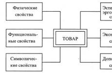
The functional diagram of the control of an asynchronous motor with a squirrel-cage rotor is shown in Figure 1.
Fig. 1. Functional diagram of asynchronous motor control.
Three-phase alternating current is supplied to the circuit breaker, which is used to connect a three-phase asynchronous motor. In addition to the contact system, the circuit breaker has combined releases (thermal and electromagnetic), which ensures automatic shutdown in case of prolonged overload and short circuit. From the circuit breaker, power is supplied to the magnetic starter. Magnetic starter - a device for remote control of the engine. It starts, stops and protects the motor from overheating and severe voltage drop. The main part of the magnetic starter is a three-pole electromagnetic contactor. From the magnetic starter, control is transferred to a three-phase asynchronous AC motor. The asynchronous motor is simple in design and easy to maintain. It consists of two main parts - the stator - the fixed part and the rotor - the rotating part. The stator has grooves in which a three-phase stator winding connected to the AC mains is placed. This winding is designed to create a rotating circular magnetic field. The rotation of the circular magnetic field is provided by a phase shift relative to each other of each of the three three-phase current systems by an angle equal to 120 degrees.
The stator windings for connection to the mains voltage 220V are connected by a triangle (Fig. 8). Depending on the type of rotor winding, machines can be with a phase and squirrel-cage rotor. Despite the fact that the motor with a phase rotor has the best starting and regulating properties, the motor with a squirrel-cage rotor is simpler and more reliable in operation, and also cheaper. I chose a squirrel-cage motor because most motors in the industry today are squirrel-cage motors. The winding of the rotor is carried out as a squirrel wheel, hot aluminum is poured into the grooves of the rotor under pressure. The rotor winding conductors are connected to form a three-phase system. The motor drives the fan. Fans used on ships are distinguished depending on the pressure they create. The fan mounted in the circuit is a low pressure fan. Usually fans are not regulated or reversed, so their drive has the simplest control scheme, which is reduced to start, stop and protection.
principled circuit diagram of non-reversible control of a three-phase asynchronous electric motor with a squirrel-cage rotor by means of an automatic switch and a magnetic starter with a two-pole thermal relay is shown in Figure 2.
From the power board, power is supplied to the circuit breaker with thermal and electromagnetic overcurrent releases. The magnetic starter circuit is drawn up in compliance with the recommended conventional graphic designations for the elements of automatic motor control circuits. Here, all elements of the same apparatus are designated by the same letters.
Fig. 2. Scheme of control of an asynchronous motor with a squirrel-cage rotor winding.
So, the main closing contacts of a linear three-pole contactor located in the power circuit, its coil and auxiliary closing contacts located in the control circuit are marked with the letters KL. The heating elements of the thermal relay included in the power circuit, and the remaining break contacts with manual reset of the same relay to their original position, which are in the control circuit, are marked with the letters RT. When the three-pole switch is turned on, after pressing the start button CNP, the coil of the linear three-pole contactor KL is turned on and its main closing contacts KL connect the stator winding of the three-phase asynchronous motor AD to the supply network, as a result of which the rotor starts to rotate. At the same time, the auxiliary closing contacts of the KL are closed, shunting the start button of the KnP, which allows it to be released. Pressing the stop button KNS disconnects the power supply circuit of the CL coil, as a result of which the contactor armature drops out, the main make contacts of the CL open and the motor stator winding is disconnected from the mains.
2.2 The main elements of the circuit and their purpose
15.09.2014
To control asynchronous electric motors, relay-contactor devices are used that implement typical starting, reverse, braking, and stopping circuits of the electric drive.
On the basis of typical relay-contactor control schemes, control schemes for electric drives of production mechanisms are developed. Starting of asynchronous motors with a small power squirrel-cage rotor is usually carried out using magnetic starters. In this case, the magnetic starter consists of an AC contactor, two electrothermal relays built into it.
The simplest control scheme for an asynchronous electric motor with a squirrel-cage rotor. The circuit uses the power supply of power circuits and control circuits from a source of the same voltage (Fig. 4.9). To improve the reliability of the operation of relay contactor devices, mostly designed for low voltage, and to improve the safety of operation, circuits with power supply of control circuits from a low voltage source are used.
If the switch S1 is turned on, then to start the electric motor, you must press the button S2 ("start"). In this case, the coil of the contactor K1M will receive power, the main contacts K1 (1-3) M in the power circuit will close and the motor stator will be connected to the network. The electric motor will start to rotate. At the same time, the make auxiliary contact K1A closes in the control circuit, bypassing the button S2 (“start”), after which this button does not need to be kept pressed, since the coil circuit of the KlM contactor remains closed. Button S2 is self-returning and returns to its original open state due to the action of the spring.
To disconnect the electric motor from the network, the button S3 (“stop”) is pressed. The coil of the contactor K1M is de-energized and the closing contacts K1(1-3)M disconnect the stator windings from the mains. At the same time, auxiliary contact K1A opens. The circuit returns to its original, normal state. The rotation of the electric motor stops.
The scheme provides protection of the motor and control circuit against short circuits by fuses F 1(1-3), protection against motor overload by two electrothermal relays F2(1-2). The spring drive of the contacts of the magnetic starter K 1 (1-3) M, K1A for opening implements the so-called zero protection, which, in the event of a power failure or a significant decrease in voltage, disconnects the motor from the mains. After the normal voltage is restored, the engine will not start spontaneously.
More precise protection against undervoltage or loss of voltage can be performed using an undervoltage relay, the coil of which is connected to two phases of the power circuit, and its normally open contact is connected in series with the contactor coil. In these schemes, instead of installing circuit breakers with fuses at the input, air automata are used.
Scheme of control of an asynchronous electric motor with a squirrel-cage rotor using a magnetic starter and an air circuit breaker. The F1 circuit breaker eliminates the possibility of a single phase break from protection operation during a single-phase short circuit, as happens when fuses are installed (Fig. 4.10). There is no need to replace the elements in the fuses when their fuse burns out.

In electric motor control circuits, automatic machines with electromagnetic releases or with electromagnetic and electrothermal releases are used. Electromagnetic type releases are characterized by an irregular cutoff equal to ten times the current and serve to protect against short-circuit currents. Electrothermal releases have an inverse time characteristic of current. Thus, a release with a rated current of 50 A trips at a 1.5-fold load after 1 hour, and at a 4-fold load - after 20 s. Electrothermal releases do not protect the motor from overheating during overloads of 20 - 30%, but they can protect the motor and the power circuit from overheating by starting current when the drive mechanism is stalled. Therefore, to protect electric motors from prolonged overloads, when using a circuit breaker with an electrothermal release of this type, additional electrothermal relays are used, as well as when using a circuit breaker with an electromagnetic release. Many circuit breakers, such as AP-50, protect the motor from both short circuit currents and overloads. The principles of operation of the circuits (see Fig. 4.9, 4.10) for starting and stopping are similar. These circuits are widely used to control non-reversible electric drives of conveyors, blowers, fans, pumps, woodworking and grinding machines.
Schemes of control of an asynchronous motor with a squirrel-cage rotor with a reversible magnetic starter. This scheme is used in cases where it is necessary to change the direction of rotation of the electric drive (Fig. 4.11), for example, in the drive of electric winches, roller tables, machine feed mechanisms, etc. The motors are controlled by a reversing magnetic starter. Turning on the engine for rotation "forward" is carried out by pressing the button S1. The coil of contactor K1M will be energized and the closing main contacts K1(1-3)M will connect the motor to the mains. To switch the electric motor, it is necessary to press the button S3 (“stop”), and then the button S2 (“back”), which will cause the K1M contactor to turn off and the K2M contactor to turn on. In this case, as can be seen from the diagram, two phases on the stator will switch, i.e. the motor will reverse rotation. To avoid a short circuit in the stator circuit between the first and third phases due to erroneous simultaneous pressing of both start buttons S1 and S2, reversing magnetic starters have a lever mechanical interlock (not shown in the diagram), which prevents one contactor from being drawn in if the other is on. To increase reliability, in addition to mechanical blocking, the circuit provides for electrical blocking, which is carried out using breaking auxiliary contacts K1A.2 and K2A.2. Typically, a reversing magnetic starter consists of two contactors enclosed in one housing.
In practice, the reverse circuit of asynchronous squirrel-cage electric motors is also used using two separate non-reversing magnetic starters. Ho, to eliminate the possibility of a short circuit between the first and third phases of the power circuit from the simultaneous switching on of both starters, double-circuit buttons are used. For example, when the S1 button (“forward”) is pressed, the coil circuit of the K1M contactors is closed, and the K2M coil circuit is additionally opened. (The principle of operation of double-circuit buttons is shown in Fig. 4.12.) Reversal of DC motors is carried out by changing the polarity of the power circuit voltage.
Control circuit of a two-speed asynchronous electric motor with a squirrel-cage rotor. Such a scheme is shown in Fig. 4.12. The drive can have two speeds. Reduced speed is obtained by connecting the stator windings to a triangle, which is done by pressing the double-circuit button S3 and turning on the short-circuit contactor with the closure of three power contacts K3. At the same time, the auxiliary contact K3A closes, shunting the S3 button, and K3A, the auxiliary contact in the K4 coil circuit, opens.
Increased speed is obtained by connecting the windings to a double star, which is realized by pressing the double-circuit button S4. In this case, the contactor coil K3 is de-energized, the short circuit contacts in the power circuit open, the auxiliary contact K3A opens, shunting the S3 button, and the auxiliary contact K3A closes in the circuit of the coil K4.
By further pressing (moving) the S4 button, the coil circuit of the contactor K4 is closed, five K4 contacts in the power circuit are closed, the stator winding will be connected to a double star. At the same time, auxiliary contact K4A closes, bypassing button S4, and auxiliary contact K4A opens in the coil circuit of contactor K3. Typically, AC contactors have three power contacts, in the double star stator connection diagram, five power contacts K4 are shown. In this case, the coil of the additional contactor is switched on in parallel with the coil of contactor K4.
After the preliminary connection of the stator windings, the motor is started using contactors K1 and K2 for forward or reverse rotation. The contactors K1 or K2 are switched on by pressing the button S1 or S2 respectively. The use of double-circuit pushbuttons makes it possible to carry out an additional electrical blocking, which excludes the simultaneous activation of contactors K1 and K2, as well as K3 and K4.
The circuit provides the ability to switch from one speed to another when the electric motor rotates forward or backward without pressing the S5 ("stop") button. When the S5 button is pressed, the coils of the switched on contactors are de-energized and the circuit returns to its original, normal state.
The considered scheme is the basis for constructing control schemes for electric motors of two-speed conveyors for supplying crosscutting units, sorting conveyors, etc.
Consider the issues of braking electric motors. When the stator windings are disconnected from the mains, the rotor of the electric motor with the working mechanism, for example, the saw blade of the sleeper machine, continues to rotate by inertia for a relatively long time. To eliminate this phenomenon, in drives with asynchronous electric motors, depending on their power and purpose, anti-switching braking, frictional braking and dynamic braking are used.
Scheme of control of an asynchronous electric motor with a squirrel-cage rotor using anti-switching braking. Such a scheme is shown in Fig. 4.13. Reverse braking circuits use an EM speed control relay (PKC) mechanically coupled to the motor shaft; its NO contact EA closes at a certain angular velocity of the motor. When the motor rotor is stationary and its rotation speed is less than 10 ... 15% of the nominal, the EA relay contact is open. By pressing the SI button, the contactor K1M is turned on, the power contacts K1 (1-3) M are closed and the motor starts up, the auxiliary contact K1A.1 closes, shunting the S1 button. The opening auxiliary contact A7A.2 simultaneously breaks the power supply circuit of the coil of the K2M contactor, and somewhat later, with an increase in the engine speed, the contact of the speed relay EA closes. Therefore, the K2M contactor does not turn on during this period.
The electric motor is disconnected from the network with anti-switching braking by pressing the S2 button (“stop”). In this case, the coil of the contactor K1M is de-energized, the power contacts K1 (1-3) M open, the auxiliary contact K1A.1, which shunts the start button S1, opens. At the same time, the NC auxiliary contact K1A.2 closes. In this case, the motor rotates by inertia and the contact of the relay EA is closed, therefore, the coil of the contactor K2A will receive power, the main contacts K2 (1-3) M will close, the auxiliary contact K2A will open in the circuit of the coil K1M. The stator windings will be connected to the network to reverse the rotation of the rotor. The rotor instantly slows down and at a rotation speed close to zero, the contact of the speed relay EA opens, the coil of the K2M contactor is de-energized, the main contacts K2 (1-3) M open, the auxiliary contact K2A closes. The engine is stopped and disconnected from the mains. The circuit will be in its original position.
The considered typical circuit of braking by opposition is the basis for constructing control circuits for electric motors of sharpening machines for chain, circular, frame saws, circuits for edgers, etc. Braking by opposition provides a hard, instantaneous stop of the drive and is usually used for low power electric motors.
Scheme of frictional braking of an asynchronous electric motor of a lifting mechanism. Such a scheme is shown in Fig. 4.14. According to the rules technical operation lifting mechanisms in the off state, the drive and the lifting mechanism must be reliably braked.
The simplified diagram conventionally shows a single-sided shoe brake T with a spring-loaded brake pulley clamp.
When starting the motor, the button S1 (“start”) is pressed, the coil of the contactor K1M will be energized, three contacts K1 (1-3) M in the power circuit and the auxiliary contact K1A will close. The stator of the electric motor and the winding of the electromagnet Y will be simultaneously connected to the network. The Y solenoid will simultaneously move the shoe brake away from the pulley and deform the spring. The motor rotates unbraked.
By pressing the button S2 ("stop"), the coil of the contactor K1M is de-energized, the main contacts in the power circuit K1 (1-3) M and the auxiliary contact K1A are opened. The stator of the electric motor and the winding of the electromagnet U are disconnected from the network, the spring-driven shoe brake rigidly fixes the rotor of the electric motor with the lifting mechanism. The use of a reversible magnetic starter makes it possible to obtain a friction braking circuit for the mechanism's electric drive both for lifting and lowering the load.
Scheme of frictional braking of an asynchronous electric motor of machine tools. Such a scheme is shown in Fig. 4.15. In the normal (disconnected) state, the rotor of the electric motor is disengaged under the action of a spring drive. This allows you to change tools, set up the machine with a slight turn of the drive shaft and the rotor of the electric motor.
The electric motor is connected to the network using the S1 button, contact K1A and power contacts K1 (1-3) M. The electric drive of the machine is stopped by pressing the double-circuit button S2 (“stop”). In this case, the coil of the contactor K1M is de-energized, the main contacts in the power circuit K1 (1-3) M and the auxiliary contact K1A open. The electric motor is disconnected from the network, continuing to rotate by inertia.
When the S2 button is pressed further, the coil circuit of the K2M contactor is closed, the contacts K2 (1-2) M are closed, the electromagnet Y tightens the shoe brake. The S2 button is released and assumes its original position, the K2M contactor is de-energized, the K2(1-2)M contacts open. The motor stator and electromagnet are disconnected from the mains, the drive is stopped and disengaged. This the simplest circuit is the basis for the development of friction braking schemes for machine tool electric motors, which take into account the need for reverse, protective guards, and signaling.
Scheme for controlling an asynchronous motor using dynamic braking. Such a scheme is shown in Fig. 4.16. Dynamic braking, in contrast to braking by counter-induction and the frictional method, is a smooth, soft braking. The electric motor is connected to the network by pressing the SI (“start”) button. The contactor K1M will be turned on, the three main contacts K1 (1-3) M in the power circuit will close, the auxiliary contact K1A.1 will close, the contact K1A.2 will open, the contact K1A.3 will close, after which the time relay D1M will turn on and close its contact RTD in the coil circuit of the contactor K2M, which was opened a little earlier by the contact K1A.2.
The motor stator is disconnected from the AC network and braking is carried out by pressing the S2 (“stop”) button. Contactor K1M loses power, main contacts K1(1-3)M open, auxiliary contacts K1A.1, K1A.3 open, and contact K1A.2 closes. The coil of the D1M time relay loses power, however, the closing contact of the RTD, being previously closed, will open with a time delay that slightly exceeds the duration of the engine braking. When the K1A.2 contact is closed, the K2M contactor coil will receive power, the K2A blocking auxiliary contact will open and the K2(1-2)M contacts will close. The stator winding is supplied with direct current. The winding creates a magnetic flux that is stationary in space. EMF is induced in the rotor rotating by inertia.
The interaction of the rotor currents caused by these EMFs with a stationary magnetic flux creates a braking torque of the motor

where Mn is the rated torque of the motor; ns - synchronous speed of the motor; I "p - the rotor current reduced to the stator; R" p - the full active resistance of the rotor, reduced to the stator; nd - relative speed of the engine, nd = n/nс.
After opening the contact of the RDT time relay, the circuit returns to its initial state, the engine stops smoothly. An additional resistor Rt is used to limit the direct current. On the basis of this scheme, electric motor control schemes for sawmill frames, sleeper cutters and other large circular saw machines were created.
Scheme of thyristor control of starting and braking of an asynchronous motor with a squirrel-cage rotor. Such a scheme is shown in Fig. 4.17. In a typical circuit of open-loop control of an asynchronous motor with a squirrel-cage rotor, thyristors are used as power elements included in the stator circuit of the motor in combination with relay-contact devices in the control circuit. Thyristors act as power switches and, moreover, easily allow the required rate of voltage change on the motor stator to be carried out by adjusting the thyristor switching angle.
At start-up, a smooth change in the thyristor switching angle makes it possible to change the voltage applied to the stator from zero to the nominal voltage, thereby limiting the motor currents and torque. The circuit contains a dynamic braking device in the form of a damping circuit. The use of a shunt thyristor, which closes the current circuit between two phases, leads to an increase in the constant current component, which creates sufficient braking torque in the region of high angular velocity.
Consider typical scheme a complete device consisting in the power section of a group of thyristors VS1 ... VS4 connected in anti-parallel in phases A and C and one short-circuited thyristor between phases A and B - V5 to control an asynchronous motor M. The circuit includes a control unit for thyristors BU and relay- control contact.
By pressing the S1 button, the K1M and K2M relays are turned on, pulses shifted by 60 ° relative to the supply voltage are applied to the control electrodes of the thyristors VS1 ... VS4. Reduced voltage is applied to the motor stator windings, starting current and starting torque are reduced. The rotor of the engine increases the speed of rotation, accelerates. The opening contact of the relay K1.2 turns off the relay K3M with a time delay depending on the parameters of the resistor R7 and capacitor C4. The opening contacts of the K3M relay shunt the corresponding resistors in the thyristor control unit BU, and the full mains voltage is applied to the stator.
To stop the engine, the S3 button is pressed, the relay control circuit is de-energized, the thyristors VS1 ... VS4 are de-energized and the voltage is removed from the engine stator. At the same time, due to the energy stored by the capacitor C5, the K4M relay is switched on for the braking time, which, with its contacts K4.2 and K4.3, turns on the thyristors VS2 and VS5. On phases A and B, a half-wave rectification current flows into the motor stator windings, which provides effective dynamic braking.
The current strength, and hence the dynamic braking time, is regulated by resistors R1 and R3. This circuit also has a stepping mode. When the S2 button is pressed, the K5M relay is turned on, which, with its contacts KS.3 and K5.4, turns on the thyristors VS2 and VS5. In this case, a half-wave rectification current flows through phases A and B into the motor stator windings. When the S2 button is released, the K5M relay and thyristors VS2 and VS5 turn off; at the same time, for a short time, due to the energy stored in the capacitor Sb, the relay is turned on, which, with its contact K6.2, turns on the thyristor VS3, and the motor rotor rotates by a certain angle due to the rotation of the resulting stator flux vector by approximately the same angle.
The turning step depends on the mains voltage, the static load moment, the moment of inertia of the drive and the average value of the rectified current. The implementation of the step-by-step mode of operation of the engine is carried out after it is stopped, since the K5M relay can initially be turned on only after the NC contacts K1.5, K4.1 are closed. The stepping mode of the motor creates favorable conditions adjustments.
Scheme of control of asynchronous electric motors with a phase rotor as a function of time. Such a scheme is shown in Fig. 4.18. Protection of the power circuits of the motor against short circuit currents is carried out using the maximum current relay FI, F2, F3; overload protection - electrothermal relays F4(1-2), heating elements which are connected through current transformers TT1, TT2. The control circuits are protected by an F5 circuit breaker with overcurrent protection.
When the SI knife switch and the FS circuit breaker are turned on, the D1M time relay will be energized and its closing contacts D1A.1, D1A.2 will close, thereby preparing the circuit for switching on the D2M time relay and the K1M contactor. Opening contact D1A.3 will open and turn off the circuit of the coils of the acceleration contactors K2M, R3M, K4M.
The next time you press the button S2 ("start") through the previously closed contact D1A.2, the contactor K1M will turn on, the main contacts K1 (1-3) M will close in the power circuit, voltage will be applied to the stator winding of the motor M. In this case, all starting resistors are included in the rotor winding. The engine starts at the first rheostatic characteristic. At the same time, the auxiliary contact K1A.3 will close, shunting the start button, and contact K1A.2 will close, through which power is supplied to the coil circuit of the time relay D2M, D3M. The opening auxiliary contact K1A.1 will turn off the D1M relay circuit, which releases the armature with a time delay when its coil is turned off. Therefore, D2M will not immediately turn on and its opening contact D2A.1 will be open.
It should be noted that the NC contact D1A.3 is still open; after the exposure time of the relay D1M, its closing contact D1A.1 (and also D1A.2) will open, and the opening contact D1A.Z will close. As a result of these switchings, the K2M contactor will turn on in the control circuit and the first starting stage of the resistor will be shunted - the motor will switch from the first rheostatic characteristic to the second one, accelerating to a higher angular velocity. In addition, the time relay D2M will turn off and its opening contact with a time delay D2A.1 will close the coil circuit of the K3M contactor, which will work and close its contacts K3 (1-2) M, i.e. the second starting stage of the resistor is shunted - the motor switches to the third rheostatic characteristic.
Finally, after opening the closing contact D2A.1 with a time delay, the D3M relay will turn off - with a time delay for which the D3M relay is configured (corresponding to the engine start time on the last rheostatic characteristic), its contact D3A.1 will close, the K4M contactor will turn on and close its contacts K4(1-3)M. The rotor winding will be short-circuited and the motor will finish its acceleration according to its natural characteristic. This is how it ends step start induction motor controlled as a function of time electromagnetic relays time D1M, D2M, D3M.
The engine is stopped by pressing the S3 button. The circuit is used to drive mechanisms that do not require reverse, the duration of braking of which after turning off the engine is not significant. In particular, on the basis of this scheme, control schemes for the main electric motor of sawmill frames are created.
Hello, dear visitors and guests of the site.
Today Dranitsyn Kirill Eduardovich, a student of SBEI SPO "KPK" in Chernushka, Perm Territory, sent his work to the competition "".
So, I beg your attention.
Equipment:
1. general purpose.

2. (to start, stop the engine).
3. Thermal relay TRN (for squirrel-cage rotor against overloads).
4. Start/stop button.

Work tool:
- flat screwdriver
- side cutters
- solid
- round nose pliers
- pliers
- three-phase plug

Scheme of irreversible start of an asynchronous motor with a squirrel-cage rotor

Before starting work, I would like to explain ordinary concepts for understanding the circuit:
- normally closed contact in the start / stop button under the numbers (3-4)
- normally open contact in the start/stop button under the numbers (1-2)

Algorithm (execution order) for assembling the circuit of non-reversible start-up of an asynchronous motor (IM)
1. Power circuit:
1.1. We take the extreme 2 wires (phase A and C) coming from the engine

1.2. We connect these wires to the upper contacts of the thermal relay


1.3. We connect the third wire from the engine to the magnetic starter, connecting it to pin 3 (phase B)

1.4. We connect the lower contacts of the thermal relay with a magnetic starter

1.5. We connect one lower contact of the thermal relay with contact 1 on the magnetic starter

1.6. We connect the other lower contact of the thermal relay to pin 5 on the magnetic starter

2. Control circuit:
2.1. Contact 6 on the magnetic starter is connected by a wire to the normally closed contact of the "Stop" button

Normally closed contacts on the "Stop" button under the numbers 3 and 4.

2.2. We make a jumper from the normally closed contact of the "Stop" button to the normally open contact of the "Start" button

2.3. We block the normally open contact: we connect contact 2 of the "Start" button with the auxiliary contact of the magnetic starter 13


2.4. We connect the normally open contact 1 of the "Start" button with the auxiliary contact of the magnetic starter 14


2.5. With a jumper we connect the block contact of the magnetic starter 13 with the magnetic starter coil (contact - A2)

2.6. From the magnetic starter coil (contact A1), we supply power to normally closed contacts

2.8. We connect the power cord to the contacts of the magnetic starter - 2, 4, 6


2.9. Before starting, check the circuit again!

2.10. We start the engine.
P.S. If you have questions about starting diagram of an asynchronous motor with a squirrel-cage rotor, then ask them in the comments to this article.