How to make a multi-stage gauss gun. Powerful do-it-yourself gauss cannon
Possessing weapons that even in computer games can only be found in the laboratory of a mad scientist or near a time portal to the future is cool. To watch how people indifferent to technology involuntarily fix their eyes on the device, and avid gamers hastily pick up their jaw from the floor - for this it is worth spending a day on assembly do-it-yourself gauss guns.
As usual, we decided to start with the simplest design – single coil induction gun. Experiments with multi-stage acceleration of the projectile were left to experienced electronics engineers who were able to build a complex switching system on powerful thyristors and fine-tune the moments of sequential switching of coils. Instead, we focused on the possibility of preparing a dish with ingredients that are widely available.
So, in order to build a Gauss cannon, first of all you have to go shopping. in the radio store homemade need to buy a few capacitors with tension 350-400V and total capacity 1000–2000 microfarads, enamelled copper wire diameter 0.8mm, battery compartments for « crowns» and two 1.5 volt type C batteries, toggle switch and button. In photo products, take five disposable cameras Kodak, in auto parts - the simplest four-pin relay from "Zhiguli", in "products" - a pack straws for cocktails, and in "toys" - a plastic pistol, machine gun, shotgun, gun or any other gun that you want to turn into a weapon of the future.

We wind on the mustache ...
The main power element of our gun - inductor. With its manufacture, it is worth starting the assembly of the gun. Take a length of straw 30 mm and two large washers(plastic or cardboard), assemble them into a reel using a screw and nut. Start winding the enameled wire around it carefully, coil by coil (with a large wire diameter, this is quite simple). Be careful not to sharply bend the wire, do not damage the insulation. After finishing the first layer, pour it superglue and start winding the next one. Do this with every layer. All you need to wind 12 layers. Then you can disassemble the reel, remove the washers and put the coil on a long straw, which will serve as a barrel. One end of the straw should be plugged. The finished coil is easy to check by connecting it to 9 volt battery: if it holds a paper clip on its weight, then you have succeeded. You can insert a straw into the coil and test it as a solenoid: it should actively draw a piece of paper clip into itself, and even throw it out of the barrel for a pulse when connected. 20–30 cm.
We dissect values
For the formation of a powerful electrical impulse, it is the best suited (in this opinion, we are in solidarity with the creators of the most powerful laboratory railguns). Capacitors are good not only for their high energy capacity, but also for the ability to give up all the energy in a very short time, before the projectile reaches the center of the coil. However, the capacitors need to be charged somehow. Fortunately, we need Charger is in any camera: a capacitor is used there to form a high-voltage pulse for the ignition electrode of the flash. Disposable cameras work best for us, because the capacitor and "charger" are the only electrical components they have, which means that getting the charging circuit out of them is a breeze.
Disassembling a disposable camera is the stage at which it is worth starting to show caution. When opening the case, try don't touch the elements electrical circuit A: The capacitor can store charge for a long time. Having gained access to the capacitor, the first thing close its terminals with a screwdriver with a dielectric handle . Only then can you touch the board without fear of getting an electric shock. Remove the battery clips from the charging circuit, unsolder the capacitor, jumper to the contacts of the charge button - we will no longer need it. Prepare at least five charging boards. Pay attention to the location of the conductive tracks on the board: you can connect to the same circuit elements in different places.
Setting priorities
Capacitor capacitance selection is a matter of compromise between shot energy and gun loading time. We settled on four capacitors 470 micro farads (400 V) connected in parallel. Before each shot, we for about minutes we are waiting for the signal of the LEDs on the charging circuits, reporting that the voltage in the capacitors has reached the prescribed 330 V. You can speed up the charging process by connecting several 3-volt battery modules in parallel to the charging circuits. However, it should be borne in mind that powerful "C" type batteries have excess current for weak camera circuits. To prevent the transistors on the boards from burning out, there should be 3-5 charging circuits connected in parallel for each 3-volt assembly. On our gun, only one battery compartment is connected to the "charges". All others serve as spare magazines.
Defining security zones
We would not advise anyone to hold a button under their finger that discharges a battery of 400-volt capacitors. To control the descent, it is better to install relay. Its control circuit is connected to a 9-volt battery through the release button, and the controlled circuit is connected to the circuit between the coil and the capacitors. It will help to assemble the gun correctly circuit diagram. When assembling a high-voltage circuit, use a wire with a cross section of at least millimeter, any thin wires are suitable for the charging and control circuits. As you experiment with the circuit, remember: capacitors may have a residual charge. Discharge them with a short circuit before touching them.
 Artem
Artem Summing up
The firing process looks like this:
- turn on the power switch;
- waiting for the bright glow of the LEDs;
- we lower the projectile into the barrel so that it is slightly behind the coil;
- turn off the power so that when fired, the batteries do not take energy on themselves; aim and press the release button.
The result largely depends on the mass of the projectile.
Be careful, the gun represents real danger.
There are standard stages of growth that every true radio amateur goes through: flasher, buzzer, power supply, amplifier, and so on. Somewhere in the beginning all sorts of shockers, teslas and gausses were wormed their way. But in my case, the assembly of the Gauss gun struck even when other normal people have been soldering oscilloscopes and Arduins for a long time. I guess I didn't play enough when I was a kid :-)
In short, I sat for 3 days on the forums, picked up the theory of electromagnetic throwing weapons, collected voltage converter circuits for charging capacitors and got down to business.
Different Inverter Circuits for Gauss


Here are a few typical schemes, allowing you to get the necessary 400 from 5-12 volt batteries to charge the capacitor, which, when discharged onto the coil, will create a powerful magnetic field that pushes the projectile. This will make Gauss wearable - regardless of the 220 V outlet. Since the batteries were only 4.2 volts on hand - I settled on the lowest voltage DC-DC inverter circuit.

Here the turns have 5 PEL-0.8 primary and 300 PEL-0.2 secondary winding. For assembly, I prepared a beautiful transformer from the ATX power supply unit, which, unfortunately, did not work ...


The circuit started only with a 20 mm ferrite ring from a Chinese electronic transformer. Just finished the windings feedback and everything worked even from 1 volt! Read more. True, further experiments were not encouraging: no matter how I tried to wind different coils on tubes, there was no sense. Someone talked about shot through plywood 2 mm, but this is not my case ...


Unfortunately it's not mine.)
And after I saw the powerful ones, I changed my plans altogether, and so that the body, cut from a plastic cable channel with a handle based on a nickel-plated furniture leg, would not disappear, I decided to put a stun gun from a Chinese flashlight, the flashlight itself and a laser sight from a red pointer. This is the vinaigrette.


The shocker was in an LED flashlight and had not worked for a long time - nickel-cadmium batteries stopped accumulating current. Therefore, I stuffed all this stuffing into a common case, bringing out the buttons and control toggle switches.


The result was a shocker-lantern with a laser sight, in the form of a futuristic blaster. I gave it to my son - he runs, shoots.


Later, I’ll put a voice recording board ordered on Ali for $ 1.5 into the free space, capable of recording a musical fragment such as a laser shot, battle sounds, etc. But this is already
The project was started in 2011. It was a project involving a fully autonomous automatic system for recreational purposes, with a projectile energy of the order of 6-7J, which is comparable to pneumatics. It was planned 3 automatic stages with launch from optical sensors, plus a powerful injector-drummer sending a projectile from the magazine into the barrel.
The layout was planned like this:
That is, the classic Bullpup, which made it possible to carry heavy batteries into the butt and thereby shift the center of gravity closer to the handle.
The schema looks like this:
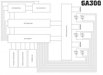
The control unit was subsequently divided into a power unit control unit and a general control unit. The capacitor unit and the switching unit were combined into one. Back-up systems were also developed. Of these, a control unit for a power unit, a power unit, a converter, a voltage distributor, and part of the display unit were assembled.
Represents 3 comparators with optical sensors.
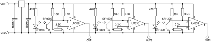
Each sensor has its own comparator. This is done to increase reliability, so if one microcircuit fails, only one stage will fail, and not 2. When the sensor beam is blocked by a projectile, the resistance of the phototransistor changes and the comparator is triggered. With classical thyristor switching, thyristor control outputs can be connected directly to comparator outputs.
Sensors must be installed as follows:

And the device looks like this:

The power block has the following simple circuit:

Capacitors C1-C4 have a voltage of 450V and a capacity of 560uF. Diodes VD1-VD5 are used of type HER307 / Power thyristors VT1-VT4 of type 70TPS12 are used as switching.

The assembled unit connected to the control unit in the photo below:

The converter was used low-voltage, you can learn more about it

The voltage distribution unit is implemented by a banal capacitor filter with a power switch and an indicator that notifies the battery charging process. The block has 2 outputs - the first is power, the second is for everything else. It also has leads for connecting a charger.

In the photo, the distribution block is on the far right from the top:

In the lower left corner is a backup converter, it was assembled according to the simplest scheme on NE555 and IRL3705 and has a power of about 40W. It was supposed to be used with a separate small battery, including a backup system in case of failure of the main battery or the discharge of the main battery.
Using a backup converter, preliminary checks of the coils were made and the possibility of using lead batteries was checked. In the video, the single-stage model shoots a pine plank. A bullet with a special tip of increased penetrating power enters the tree by 5mm.
Within the framework of the project, a universal stage was also developed as the main unit for the following projects.
This circuit is a block for an electromagnetic accelerator, on the basis of which it is possible to assemble a multistage accelerator with up to 20 stages. The stage has a classic thyristor switching and an optical sensor. The energy pumped into the capacitors is 100J. Efficiency is about 2%.

A 70W converter with a NE555 master oscillator and an IRL3705 power field effect transistor was used. Between the transistor and the output of the microcircuit, a follower on a complementary pair of transistors is provided, which is necessary to reduce the load on the microcircuit. The comparator of the optical sensor is assembled on the LM358 chip, it controls the thyristor by connecting capacitors to the winding when the projectile passes through the sensor. Good snubber circuits are used in parallel with the transformer and accelerating coil.
Methods for increasing efficiency
Methods for increasing efficiency, such as a magnetic circuit, cooling coils and energy recovery, were also considered. I will tell you more about the latter.
Gauss Gun has a very low efficiency, people working in this area have long been looking for ways to increase efficiency. One of these methods is recovery. Its essence is to return unused energy in the coil back to the capacitors. Thus, the energy of the induced reverse pulse does not go anywhere and does not catch the projectile with a residual magnetic field, but is pumped back into the capacitors. In this way, you can return up to 30 percent of energy, which in turn will increase efficiency by 3-4 percent and reduce reload time, increasing the rate of fire in automatic systems. And so - the scheme on the example of a three-stage accelerator.

Transformers T1-T3 are used for galvanic isolation in the thyristor control circuit. Consider the work of one stage. We apply the charge voltage of the capacitors, through VD1 the capacitor C1 is charged to the nominal voltage, the gun is ready to fire. When a pulse is applied to the input IN1, it is transformed by the transformer T1, and enters the control outputs VT1 and VT2. VT1 and VT2 open and connect coil L1 to capacitor C1. The graph below shows the processes during the shot.
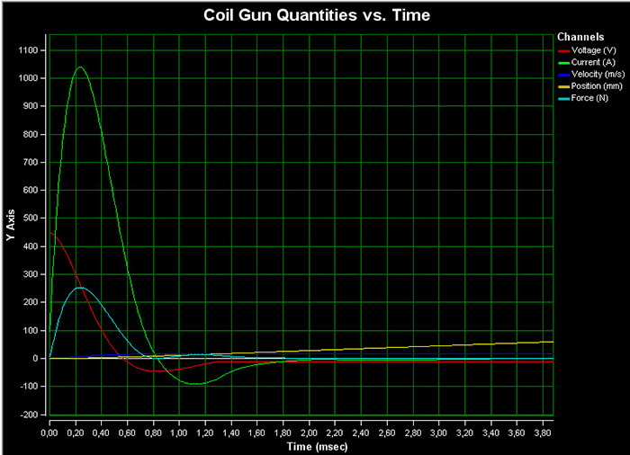
We are most interested in the part starting from 0.40ms, when the voltage becomes negative. It is this voltage that can be caught and returned to the capacitors with the help of recuperation. When the voltage becomes negative, it passes through VD4 and VD7 and is pumped into the drive of the next stage. This process also cuts off part of the magnetic impulse, which allows you to get rid of the inhibitory residual effect. The rest of the steps work like the first.
Project Status
The project and my developments in this direction were generally suspended. Probably in the near future I will continue my work in this area, but I do not promise anything.
List of radio elements
| Designation | Type of | Denomination | Quantity | Note | Score | My notepad | |
|---|---|---|---|---|---|---|---|
| Power section control unit | |||||||
| Operational amplifier | LM358 | 3 | To notepad | ||||
| Linear Regulator | 1 | To notepad | |||||
| Phototransistor | SFH309 | 3 | To notepad | ||||
| Light-emitting diode | SFH409 | 3 | To notepad | ||||
| Capacitor | 100uF | 2 | To notepad | ||||
| Resistor | 470 ohm | 3 | To notepad | ||||
| Resistor | 2.2 kOhm | 3 | To notepad | ||||
| Resistor | 3.5 kOhm | 3 | To notepad | ||||
| Resistor | 10 kOhm | 3 | To notepad | ||||
| Power block | |||||||
| VT1-VT4 | Thyristor | 70TPS12 | 4 | To notepad | |||
| VD1-VD5 | rectifier diode | HER307 | 5 | To notepad | |||
| C1-C4 | Capacitor | 560uF 450V | 4 | To notepad | |||
| L1-L4 | Inductor | 4 | To notepad | ||||
LM555 | 1 | To notepad | |||||
| Linear Regulator | L78S15CV | 1 | To notepad | ||||
| Comparator | LM393 | 2 | To notepad | ||||
| bipolar transistor | MPSA42 | 1 | To notepad | ||||
| bipolar transistor | MPSA92 | 1 | To notepad | ||||
| MOSFET transistor | IRL2505 | 1 | To notepad | ||||
| zener diode | BZX55C5V1 | 1 | To notepad | ||||
| rectifier diode | HER207 | 2 | To notepad | ||||
| rectifier diode | HER307 | 3 | To notepad | ||||
| Schottky diode | 1N5817 | 1 | To notepad | ||||
| Light-emitting diode | 2 | To notepad | |||||
| 470uF | 2 | To notepad | |||||
| electrolytic capacitor | 2200uF | 1 | To notepad | ||||
| electrolytic capacitor | 220uF | 2 | To notepad | ||||
| Capacitor | 10uF 450V | 2 | To notepad | ||||
| Capacitor | 1uF 630V | 1 | To notepad | ||||
| Capacitor | 10 nF | 2 | To notepad | ||||
| Capacitor | 100 nF | 1 | To notepad | ||||
| Resistor | 10 MΩ | 1 | To notepad | ||||
| Resistor | 300 kOhm | 1 | To notepad | ||||
| Resistor | 15 kOhm | 1 | To notepad | ||||
| Resistor | 6.8 kOhm | 1 | To notepad | ||||
| Resistor | 2.4 kOhm | 1 | To notepad | ||||
| Resistor | 1 kOhm | 3 | To notepad | ||||
| Resistor | 100 ohm | 1 | To notepad | ||||
| Resistor | 30 ohm | 2 | To notepad | ||||
| Resistor | 20 ohm | 1 | To notepad | ||||
| Resistor | 5 ohm | 2 | To notepad | ||||
| T1 | Transformer | 1 | To notepad | ||||
| Voltage distribution block | |||||||
| VD1, VD2 | Diode | 2 | To notepad | ||||
| Light-emitting diode | 1 | To notepad | |||||
| C1-C4 | Capacitor | 4 | To notepad | ||||
| R1 | Resistor | 10 ohm | 1 | To notepad | |||
| R2 | Resistor | 1 kOhm | 1 | To notepad | |||
| Switch | 1 | To notepad | |||||
| Battery | 1 | To notepad | |||||
| Programmable timer and oscillator | LM555 | 1 | To notepad | ||||
| Operational amplifier | LM358 | 1 | To notepad | ||||
| Linear Regulator | LM7812 | 1 | To notepad | ||||
| bipolar transistor | BC547 | 1 | To notepad | ||||
| bipolar transistor | BC307 | 1 | To notepad | ||||
| MOSFET transistor | AUIRL3705N | 1 | To notepad | ||||
| Phototransistor | SFH309 | 1 | To notepad | ||||
| Thyristor | 25 A | 1 | To notepad | ||||
| rectifier diode | HER207 | 3 | To notepad | ||||
| Diode | 20 A | 1 | To notepad | ||||
| Diode | 50 A | 1 | To notepad | ||||
| Light-emitting diode | SFH409 | 1 | |||||
Encyclopedic YouTube
1 / 3
✪ Particle accelerators
✪ Rotation of the torsion pendulum 1 (V.N. Samokhvalov)
✪ Oleg Sokolov about the Egyptian campaign: The Battle of Abukir, Cairo and the Dezey campaign
Subtitles
Operating principle
The parameters of the accelerating coils, projectile, and capacitors must be coordinated in such a way that, when the projectile approaches the solenoid, the magnetic field induction in the solenoid is maximum when the projectile approaches the solenoid, but drops sharply as the projectile approaches. It is worth noting that different algorithms for the operation of accelerating coils are possible.
Kinetic energy of the projectile E = m v 2 2 (\displaystyle E=(mv^(2) \over 2)) m (\displaystyle m)- projectile weight v (\displaystyle v)- its speed Energy stored in the capacitor E = C U 2 2 (\displaystyle E=(CU^(2) \over 2)) U (\displaystyle U)- capacitor voltage C (\displaystyle C)- capacitor capacity Discharge time of capacitors
This is the time it takes for the capacitor to fully discharge:
T = π L C 2 (\displaystyle T=(\pi (\sqrt (LC)) \over 2)) L (\displaystyle L)- inductance C (\displaystyle C)- capacitance Operating time of the inductorThis is the time during which the EMF of the inductor rises to its maximum value (full discharge of the capacitor) and completely drops to 0. It is equal to the upper half cycle of the sinusoid.
T = 2 π L C (\displaystyle T=2\pi (\sqrt (LC))) L (\displaystyle L)- inductance C (\displaystyle C)- capacityIt is worth noting that in the presented form, the last two formulas cannot be used to calculate the Gauss gun, if only for the reason that as the projectile moves inside the coil, its inductance changes all the time.
Application
Theoretically, it is possible to use Gauss guns to launch light satellites into orbit, since in stationary use it is possible to have a large source of energy. The main application is amateur installations, demonstration of the properties of ferromagnets. It is also quite actively used as a children's toy or developing technical creativity. homemade installation(simplicity and relative safety)
Creation
The simplest designs can be assembled from improvised materials even with school knowledge of physics
There are many websites that detail how to assemble a Gauss cannon. But it is worth remembering that the creation of weapons in some countries may be prosecuted. Therefore, before creating a Gauss cannon, it is worth considering how you will use it.
Advantages and disadvantages
The Gauss Cannon as a weapon has advantages that other types of small arms do not have. This is the absence of shells and unlimited choice of the initial speed and energy of the ammunition, the possibility of a silent shot (if the speed of a sufficiently streamlined projectile does not exceed the speed of sound), including without changing the barrel and ammunition, relatively low recoil (equal to the momentum of the projectile that has flown out, there is no additional impulse from powder gases or moving parts), theoretically, greater reliability and, in theory, wear resistance, as well as the ability to work in any conditions, including in outer space.
However, despite the apparent simplicity of the Gauss cannon, its use as a weapon is fraught with serious difficulties, the main of which is high energy costs.
The first and main difficulty is the low efficiency of the installation. Only 1-7% of the charge of the capacitors is converted into the kinetic energy of the projectile. In part, this disadvantage can be compensated for by using a multi-stage projectile acceleration system, but in any case, the efficiency rarely reaches 27%. Basically, in amateur installations, the energy stored in the form of a magnetic field is not used in any way, but is the reason for using powerful keys (often IGBT modules are used) to open the coil (Lenz's rule).
The second difficulty is the high energy consumption (due to low efficiency).
The third difficulty (follows from the first two) is the large weight and dimensions of the installation with its low efficiency.
The fourth difficulty is the rather long time of accumulative recharging of capacitors, which forces one to carry along with the Gauss gun (as a rule, a powerful rechargeable battery), as well as their high cost. It is theoretically possible to increase the efficiency if superconducting solenoids are used, but this will require a powerful cooling system, which brings additional problems and seriously affects the scope of the installation. Or use replaceable battery capacitors.
The fifth difficulty is that with an increase in the speed of the projectile, the duration of the magnetic field during the flight of the solenoid by the projectile is significantly reduced, which leads to the need not only to turn on each next coil of the multistage system in advance, but also to increase the power of its field in proportion to the reduction of this time. Usually this disadvantage is immediately ignored, since most homemade systems have either a small number of coils or insufficient bullet speed.
In conditions aquatic environment the use of a gun without a protective casing is also seriously limited - remote current induction is enough for the salt solution to dissociate on the casing with the formation of aggressive (dissolving) media, which requires additional magnetic shielding.
Thus, today the Gauss gun has no prospects as a weapon, since it is significantly inferior to other types of small arms operating on other principles. Theoretically, prospects are, of course, possible if compact and powerful sources of electric current and high-temperature superconductors (200-300 K) are created. However, a setup similar to the Gauss cannon can be used in outer space, since in vacuum and weightlessness many of the shortcomings of such installations are leveled. In particular, the military programs of the USSR and the USA considered the possibility of using installations similar to the Gauss gun on orbiting satellites to destroy other spacecraft (projectiles with a large number of small damaging parts), or objects on the earth's surface.
Hello friends! Surely some of you have already read or personally encountered the Gaussian electromagnetic accelerator, which is better known as the "Gauss Gun".
The traditional Gauss gun is built using hard-to-find or rather expensive high-capacity capacitors, and some wiring (diodes, thyristors, etc.) is also required to properly load and fire. This can be quite difficult for people who do not understand anything in radio electronics, but the desire to experiment does not allow them to sit still. In this article, I will try to talk in detail about the principle of operation of the gun and how you can assemble a Gaussian accelerator simplified to a minimum.
The main part of the gun is the coil. As a rule, it is wound independently on some dielectric non-magnetic rod, which in diameter slightly exceeds the diameter of the projectile. In the proposed design, the coil can even be wound "by eye", because the principle of operation simply does not allow any calculations to be made. It is enough to get a copper or aluminum wire with a diameter of 0.2-1 mm in lacquer or silicone insulation and wind 150-250 turns on the barrel so that the winding length of one row is about 2-3 cm. You can also use a ready-made solenoid.

When an electric current passes through a coil, a magnetic field is generated in it. Simply put, the coil turns into an electromagnet that draws in an iron projectile, and so that it does not remain in the coil, you just need to turn off the current when it enters the solenoid.
In classic guns, this is achieved through precise calculations, the use of thyristors and other components that will "cut off" the pulse at the right time. We will simply break the chain "when we can." For emergency breaking of the electrical circuit in everyday life, fuses are used, they can be used in our project, but it is more advisable to replace them with bulbs from a Christmas tree garland. They are catering low voltage, therefore, when powered from a 220V network, they instantly burn out and break the circuit.


Finished device consists of only three parts: a coil, a network cable and a light bulb connected in series to the coil.

Many will agree that using a gun in this form is extremely inconvenient and unaesthetic, and sometimes even very dangerous. So I mounted the device on a small piece of plywood. I installed separate terminals for the coil. This makes it possible to quickly change the solenoid and experiment with different options. For the light bulb, I installed two thin cut nails. The ends of the light bulb wires simply wrap around them, so the light bulb changes very quickly. Please note that the flask itself is located in a specially made hole.

The fact is that when fired, there is a big flash and sparks, so I considered it necessary to take this “stream” down a little. Scheme of a simple single-stage desktop electromagnetic mass accelerator or simply - Gauss gun. Named after the German scientist Carl Gauss. In my case, the accelerator consists of a charger, a current-limiting load, two electrolytic capacitors, a voltmeter and a solenoid.
So, let's take everything in order. Charging the gun is powered by 220 volts. Charging consists of a 1.5uF 400V capacitor. Diodes 1N4006. Output voltage 350 V.

Next comes the current-limiting load - H1, in my case an incandescent lamp, but you can use a powerful resistor of 500 - 1000 ohms. Key S1 limits the charging of capacitors. Key S2 delivers a powerful discharge of current to the solenoid, so S2 must withstand a large current, in my case I used a button from the electrical panel.

Capacitors C1 and C2, each 470 uF 400 V. In total, 940 uF 400 V is obtained. Connect the capacitors observing the polarity and voltage on them during charging. You can control the voltage on them with a voltmeter.

And now the most difficult thing in our gauss gun design is the solenoid. It is wound on a dielectric rod. The inner diameter of the trunk is 5-6 mm. The wire used PEL 0.5. The thickness of the coil is 1.5 cm. The length is 2 cm. When winding the solenoid, it is necessary to isolate each layer with super glue.

To accelerate with our electromagnetic gauss gun, we will trim nails or homemade bullets 4-5 mm thick, as long as a reel. Lighter bullets fly longer. Heavier ones fly less distance, but they have more energy. My gauss gun pierces beer cans and shoots 10-12 meters depending on the bullet.

And yet, for the accelerator it is better to select thicker wires so that there is less resistance in the circuit. Be extremely careful! During the invention of the accelerator, I was shocked several times, follow the rules of electrical safety and pay attention to the reliability of the insulation. Good luck in creativity.
Discuss the article GAUSS GUN
.
In this article, Konstantin from How-todo will show you how to make a portable Gauss Cannon.
The project was made just for fun, so there was no goal to set any records in Gaussian building.


In fact, Konstantin even became too lazy to count the coil.


Let's start by brushing up on the theory. How does the Gauss gun work.
We charge the capacitor with a high voltage and discharge it into a coil of copper wire located on the stem.
When current flows through it, a powerful electromagnetic field is created. A ferromagnetic bullet is drawn into the barrel. The charge on the capacitor is used up very quickly and, ideally, current through the coil stops flowing when the bullet is in the middle.

After that, she continues to fly by inertia.
Before proceeding to the assembly, it should be warned that you need to work very carefully with high voltage.
Especially when using such large capacitors, it can be quite dangerous.

We will make a single-stage gun.
First, because of the simplicity. Electronics in it is almost elementary.
In the manufacture of a multi-stage system, it is necessary to somehow switch the coils, calculate them, and install sensors.


Secondly, a multi-stage device simply would not fit in the intended pistol form factor.


For even now the body is full. Similar turning point pistols were taken as the basis.


The body will be printed on a 3D printer. To do this, we start with a model.


We make it in Fusion360, all files will be in the description, if suddenly someone wants to repeat.

We will try to put all the details as compactly as possible. By the way, there are very few of them.
4 18650 batteries, totaling approximately 15V.
In their seat in the model, recesses are provided for installing jumpers.

Which we will make from thick foil.
A module that boosts battery voltage to about 400 volts to charge a capacitor.

The capacitor itself, and this is a bank of 1000 microfarads 450 V.

And the last. The actual coil.


The rest of the little things like a thyristor, batteries to open it, start buttons can be placed with a canopy or glued to the wall.

So there are no separate seats for them.
For the barrel you need a non-magnetic tube.

We will use the case from a ballpoint pen. This is much simpler than let's print it on a printer and then grind it.

We wind a copper varnished wire with a diameter of 0.8 mm on the coil frame, laying insulation between each layer. Each layer must be rigidly fixed.


We wind each layer as tightly as possible, turn to turn, we make as many layers as will fit in the case.

The handle is made of wood.


The model is ready, you can start the printer.

Almost all parts are made with a 0.8mm nozzle and only the button holding the barrel is made with a 0.4mm nozzle.


Printing took about seven hours, so it turned out that only pink plastic remained.
After printing, carefully clean the model from supports. We buy primer and paint from the store.


Use acrylic paint it didn’t work out, but she refused to lay down normally even on the ground.
For painting PLA plastic, there are special sprays and paints that will hold perfectly even without preparation.
But such paints were not found, it turned out clumsy of course.
I had to paint half leaning out the window.


Let's say that an uneven surface is such a style, and in general it was planned so.
While printing is in progress and the paint dries, let's take care of the handle.
There was no wood of suitable thickness, so we will glue two pieces of parquet together.


When it is dry, we give it a rough shape with a jigsaw.


We are a little surprised that a cordless jigsaw cuts 4 cm of wood without much difficulty.

Next, with the help of a dremel and a nozzle, we round the corners.


Due to the small width of the workpiece, the inclination of the handle is not quite the same as desired.

Let's smooth out these inconveniences with ergonomics.

We overwrite the irregularities with a nozzle with sandpaper, manually go through the 400th.

After stripping, cover with oil in several layers.


We fasten the handle to the self-tapping screw, having previously drilled the channel.


With finishing sandpaper and needle files, we adjust all the details to each other so that everything closes, holds and clings as it should.


You can move on to electronics.
The first step is to install the button. Approximately estimating so that in the future it does not interfere much.


Next, assemble the battery compartment.
To do this, cut the foil into strips and glue it under the battery contacts. Batteries are connected in series.

We always check that there is a reliable contact.
When this is done, you can connect the high-voltage module through the button, and a capacitor to it.


You can even try to charge it.
We set the voltage to about 410 V, in order to discharge it to the coil without loud pops of closing contacts, you need to use a thyristor that works like a switch.

And for it to close, a small voltage of one and a half volts on the control electrode is enough.


Unfortunately, it turned out that the step-up module has a middle point, and this does not allow you to take control voltage from already installed batteries without any special tricks.
Therefore, we take a finger battery.


A small clock button serves as a trigger, switching large currents through the thyristor.


That would have been the end of it, but two thyristors could not stand such abuse.
So I had to select a more powerful thyristor, 70TPS12, it can withstand 1200-1600V and 1100A per pulse.


Since the project is still frozen for a week, we will also buy more parts in order to make a charge indicator. It can operate in two modes, lighting only one diode, shifting it, or lighting all in turn.

The second option looks more beautiful.

The scheme is quite simple, but on Ali you can buy a ready-made such module.


By adding a couple of megaohm resistors to the input of the indicator, you can connect it directly to the capacitor.
The new thyristor, as planned, easily passes powerful currents.


The only thing is that it does not close, that is, before firing, you need to turn off the charging so that the capacitor can be completely discharged, and the thyristor goes into its original state.
This could have been avoided if the converter had a half-wave rectifier.
Attempts to remake the existing success did not bring.
You can start making bullets. They must be magnetic.

You can take such wonderful dowel-nails, they have a diameter of 5.9 mm.

And the trunk fits perfectly, it remains only to cut off the hat, and sharpen it a bit.


The weight of the bullet turned out to be 7.8 g.

Speed, unfortunately, now there is nothing to measure.
We finish the assembly by gluing the body and coil.

You can test it, this toy makes holes in aluminum cans well, punches through cardboard boxes, and in general you can feel the power.

Although many claim that the Gauss cannon is silent, it does pop a little when fired, even without a bullet.

When large currents are passed through the wire of the coil, although this happens in a fraction of a second, it heats up and expands a little.
If you impregnate the coil with epoxy resin, you can partially get rid of this effect.
Homemade was presented for you by Konstantin, How-todo workshop.
Hi all. In this article, we will consider how to make a portable Gaussian electromagnetic gun assembled using a microcontroller. Well, about the Gauss gun, of course, I got excited, but there is no doubt that it is an electromagnetic gun. This device on a microcontroller was developed in order to teach beginners how to program microcontrollers using the example of constructing an electromagnetic gun with their own hands. Let's analyze some design points both in the Gauss electromagnetic gun itself and in the program for the microcontroller.
From the very beginning, you need to decide on the diameter and length of the barrel of the gun itself and the material from which it will be made. I used a plastic case with a diameter of 10 mm from under mercury thermometer, because I have it lying around idle. You can use any available material that has non-ferromagnetic properties. These are glass, plastic, copper tube, etc. The length of the barrel may depend on the number of electromagnetic coils used. In my case, four electromagnetic coils are used, the barrel length is twenty centimeters.

As for the diameter of the tube used, in the process of operation, the electromagnetic gun showed that it is necessary to take into account the diameter of the barrel relative to the projectile used. Simply put, the diameter of the barrel should not be much larger than the diameter of the projectile used. Ideally, the barrel of an electromagnetic gun should fit under the projectile itself.
The material for creating shells was the axis from the printer with a diameter of five millimeters. From this material and five blanks 2.5 centimeters long were made. Although it is also possible to use steel blanks, say, from a wire or an electrode - what can be found.
You need to pay attention to the weight of the projectile itself. The weight should be kept as low as possible. My shells are a bit heavy.

Before the creation of this gun, experiments were carried out. An empty paste from a pen was used as a barrel, a needle was used as a projectile. The needle easily pierced the cover of a magazine placed near the electromagnetic gun.
Since the original Gauss electromagnetic gun is built on the principle of charging a capacitor with a high voltage, about three hundred volts, for safety reasons, novice radio amateurs should power it with a low voltage, about twenty volts. Low voltage leads to the fact that the range of the projectile is not very long. But again, it all depends on the number of electromagnetic coils used. The more electromagnetic coils used, the greater the acceleration of the projectile in the electromagnetic gun. The diameter of the barrel also matters (the smaller the diameter of the barrel, the farther the projectile flies) and the quality of the winding of the electromagnetic coils themselves. Perhaps electromagnetic coils are the most basic in the design of an electromagnetic gun, serious attention must be paid to this in order to achieve maximum projectile flight.
I will give the parameters of my electromagnetic coils, they may be different for you. The coil is wound with a wire with a diameter of 0.2 mm. The winding length of the electromagnetic coil layer is two centimeters and contains six such rows. I did not isolate each new layer, but started winding a new layer on the previous one. Due to the fact that electromagnetic coils are powered by low voltage, you need to get the maximum Q factor of the coil. Therefore, we wind all the turns tightly to each other, turn to turn.

As for the feeder, no special explanations are needed here. Everything was soldered from waste foil textolite left over from production printed circuit boards. The pictures show everything in detail. The heart of the feeder is the SG90 servo driven by a microcontroller.

The feed rod is made of a steel bar with a diameter of 1.5 mm, an m3 nut is soldered at the end of the rod for coupling with the servo drive. A copper wire with a diameter of 1.5 mm bent at both ends is installed on the servo rocker to increase the arm.
This simple device, assembled from improvised materials, is quite enough to feed a projectile into the barrel of an electromagnetic gun. The feed rod must completely exit the loading magazine. A cracked brass post with an internal diameter of 3 mm and a length of 7 mm served as a guide for the supply rod. It was a pity to throw it away, so it came in handy, in fact, like pieces of foil textolite.
The program for the atmega16 microcontroller was created in AtmelStudio, and is a completely open source project for you. Consider some settings in the microcontroller program that will have to be made. For the most efficient operation of the electromagnetic gun, you will need to set the operating time of each electromagnetic coil in the program. The setting is done in order. First, solder the first coil into the circuit, do not connect the rest. Set the time in the program (in milliseconds).
Flash the microcontroller, and run the program on the microcontroller. The effort of the reel should be enough to pull the projectile and give the initial acceleration. Having achieved the maximum flight of the projectile, adjusting the time of the coil in the microcontroller program, connect the second coil and also adjust the time, achieving an even greater range of the projectile. Accordingly, the first coil remains on.
PORTA |=(1 PORTA &=~(1
In this way, you set up the operation of each electromagnetic coil, connecting them in order. As the number of electromagnetic coils in the Gauss electromagnetic gun device increases, the speed and, accordingly, the range of the projectile should also increase.
This painstaking procedure for setting up each coil can be avoided. But for this, it will be necessary to modernize the device of the electromagnetic gun itself by installing sensors between electromagnetic coils to track the movement of the projectile from one coil to another. Sensors in combination with a microcontroller will not only simplify the tuning process, but also increase the range of the projectile. I did not do these bells and whistles and complicate the microcontroller program. The goal was to implement an interesting and simple project using a microcontroller. How interesting it is, to judge, of course, you. To be honest, I rejoiced like a child, "threshing" from this device, and I came up with the idea of a more serious device on a microcontroller. But that's a topic for another article.
Program and scheme -
9,830 ViewsA powerful model of the famous Gauss gun, which you can make with your own hands from improvised means, is satisfied. This homemade Gauss gun is made very simply, has lightweight construction, all used parts can be found in every homemade lover and radio amateur. With the help of the coil calculation program, you can get the maximum power.
So, to make the Gauss Cannon, we need:
- Piece of plywood.
- Sheet plastic.
- Plastic tube for muzzle ∅5 mm.
- Copper wire for coil ∅0.8 mm.
- Large electrolytic capacitors
- start button
- Thyristor 70TPS12
- Batteries 4X1.5V
- Incandescent lamp and socket for it 40W
- Diode 1N4007
Assembling the body for the scheme of the Gauss gun
The shape of the case can be any, it is not necessary to adhere to the presented scheme. To give the case an aesthetic appearance, you can paint it with spray paint.


Installing parts in the housing for the Gauss Cannon
To begin with, we mount the capacitors, in this case they were fixed to plastic ties, but you can think of another mount.

Then we install the cartridge for the incandescent lamp on the outside of the housing. Don't forget to connect two power wires to it.


Then we place the battery compartment inside the case and fix it, for example, with wood screws or in another way.

Coil winding for the Gauss Cannon
To calculate the Gaussian coil, you can use the FEMM program, you can download the FEMM program from this link https://code.google.com/archive/p/femm-coilgun
Using the program is very easy, you need to enter the necessary parameters in the template, load them into the program, and at the output we get all the characteristics of the coil and the future gun as a whole, up to the speed of the projectile.
So, let's start winding! First you need to take the prepared tube and wrap paper around it using PVA glue so that the outer diameter of the tube is 6 mm.


Then we drill holes in the center of the segments and put them on the tube. Fix them with hot glue. The distance between the walls should be 25 mm.


We put the coil on the barrel and proceed to the next step ...

Scheme Gauss Cannon. Assembly

We assemble the circuit inside the case by surface mounting.

Then we install the button on the case, drill two holes and thread the wires for the coil there.

To simplify use, you can make a stand for the gun. In this case, it was made from wooden block. AT this option carriage, gaps were left along the edges of the barrel, this is necessary in order to adjust the coil, moving the coil, you can achieve the greatest power.

Cannon shells are made from a metal nail. Segments are made 24 mm long and 4 mm in diameter. Ammunition blanks need to be sharpened.


Subscribe to news