Power supply: with and without regulation, laboratory, pulsed, device, repair. Laboratory power supply: switching or linear, which one to choose? Device, circuits and their comparison How to assemble a laboratory power supply with your own hands
For radio amateurs, and modern people in general, an indispensable thing in the house is a power supply unit (PSU), because it has a very useful function - voltage and current regulation.
At the same time, few people know that it is quite possible to make such a device with due diligence and knowledge of radio electronics with your own hands. For any radio amateur who likes to tinker with electronics at home, homemade laboratory power supplies will allow him to practice his hobby without restrictions. Our article will tell you how to make an adjustable power supply with your own hands.
What you need to know
A power supply with current and voltage regulation is a must-have item in a modern home. This device, thanks to its special device, can convert the voltage and current available in the network to the level that a particular electronic device can consume. Here is an approximate scheme of work according to which you can make such a device with your own hands.
But ready-made power supplies are quite expensive to buy for specific needs. Therefore, today very often converters for voltage and current are made by hand.
Note! Homemade laboratory power supplies can have different dimensions, power ratings and other characteristics. It all depends on what kind of converter you need and for what purpose.
Professionals can easily make a powerful power supply, while beginners and amateurs can start with a simple type of device. In this case, depending on the complexity, a very different scheme can be used.
What to consider

The regulated power supply is a universal converter that can be used to connect any household or computing equipment. Without it, not a single home appliance will be able to function normally.
Such a power supply unit consists of the following components:
- transformer;
- converter;
- indicator (voltmeter and ammeter).
- transistors and other parts necessary to create a high-quality electrical network.
The diagram above shows all the components of the device.
In addition, this type of power supply must have protection for high and low current. Otherwise, any emergency situation may lead to the fact that the converter and the electrical device connected to it simply burn out. This result can also be caused by improper soldering of board components, incorrect connection or installation.
If you are a beginner, then in order to make an adjustable type of power supply with your own hands, it is better to choose a simple assembly option. One of the simple types of converter is a 0-15V power supply. It has protection against excess current in the connected load. The diagram for its assembly is located below.

Simple assembly diagram
This is, so to speak, a universal type of assembly. The diagram here is easy to understand for anyone who has held a soldering iron at least once in their hands. The advantages of this scheme include the following points:
- it consists of simple and affordable parts that can be found either on the radio market or in specialized radio electronics stores;
- simple type of assembly and further configuration;
- here the lower limit for voltage is 0.05 volts;
- dual-range protection for current indicator (at 0.05 and 1A);
- wide range for output voltages;
- high stability in the functioning of the converter.

Diode bridge
In this situation, the transformer will provide a voltage that is 3V higher than the maximum required output voltage. It follows from this that a power supply capable of regulating voltage up to 20V requires a transformer of at least 23 V.
Note! The diode bridge should be selected based on the maximum current, which will be limited by the available protection.
A 4700 µF filter capacitor will allow equipment sensitive to power supply noise to avoid background noise. To do this, you will need a compensation stabilizer with a suppression coefficient for ripples of more than 1000.
Now that we have understood the basic aspects of assembly, we need to pay attention to the requirements.
Device requirements
To create a simple, but at the same time high-quality and powerful power supply with the ability to regulate voltage and current with your own hands, you need to know what requirements exist for this type of converter.
These technical requirements look like this:
- adjustable stabilized output for 3–24 V. In this case, the current load must be at least 2 A;
- unregulated 12/24 V output. This assumes a large current load.
To fulfill the first requirement, you should use an integral stabilizer. In the second case, the output must be made after the diode bridge, so to speak, bypassing the stabilizer.
Let's start assembling
![]()
Transformer TS-150–1
Once you have determined the requirements that your permanent regulated power supply must meet, and the appropriate circuit has been selected, you can begin the assembly itself. But first of all, let's stock up on the parts we need.
For assembly you will need:
- powerful transformer. For example, TS-150–1. It is capable of delivering voltages of 12 and 24 V;
- capacitor. You can use a 10000 µF 50 V model;
- chip for stabilizer;
- strapping;
- details of the circuit (in our case, the circuit shown above).
After this, according to the diagram, we assemble an adjustable power supply with our own hands in strict accordance with all the recommendations. The sequence of actions must be followed.

Ready power supply
The following parts are used to assemble the power supply:
- germanium transistors (mostly). If you want to replace them with more modern silicon elements, then the lower MP37 should definitely remain germanium. MP36, MP37, MP38 transistors are used here;
- A current-limiting unit is assembled on the transistor. It provides monitoring of the voltage drop across the resistor.
- Zener diode D814. It determines the regulation of the maximum output voltage. It absorbs half of the output voltage;
Note! Since the D814 zener diode takes exactly half the output voltage, it should be selected to create a 0-25V output voltage of approximately 13V.
- the lower limit in the assembled power supply has a voltage indicator of only 0.05 V. This indicator is rare for more complex converter assembly circuits;
- dial indicators display current and voltage indicators.

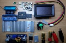
Parts for assembly
To accommodate all the parts, you must choose a steel case. It will be able to shield the transformer and power supply board. As a result, you will avoid situations of various types of interference for sensitive equipment.
The resulting converter can be safely used to power any household equipment, as well as experiments and tests carried out in a home laboratory. Also, such a device can be used to assess the performance of a car generator.
Conclusion
Using simple circuits for assembling an regulated type of power supply, you will be able to get your hands on and in the future make more complex models with your own hands. You should not take on backbreaking work, as in the end you may not get the desired result, and a homemade converter will work ineffectively, which can negatively affect both the device itself and the functionality of the electrical equipment connected to it.
If everything is done correctly, then at the end you will get an excellent power supply with voltage regulation for your home laboratory or other everyday situations.
 Selecting a street motion sensor to turn on the lights
The master whose device was described in the first part, having set out to make a power supply with regulation, did not complicate things for himself and simply used boards that were lying idle. The second option involves the use of an even more common material - an adjustment has been added to the usual block, perhaps this is a very promising solution in terms of simplicity, given that the necessary characteristics will not be lost and even the most experienced radio amateur can implement the idea with his own hands. As a bonus, there are two more options for very simple schemes with all the detailed explanations for beginners. So, there are 4 ways for you to choose from.
We'll tell you how to make an adjustable power supply from an unnecessary computer board. The master took the computer board and cut out the block that powers the RAM.
This is what he looks like.
Let's decide which parts need to be taken and which ones not, in order to cut off what is needed so that the board has all the components of the power supply. Typically, a pulse unit for supplying current to a computer consists of a microcircuit, a PWM controller, key transistors, an output inductor and an output capacitor, and an input capacitor. For some reason, the board also has an input choke. He left him too. Key transistors - maybe two, three. There is a seat for 3 transistors, but it is not used in the circuit.
The PWM controller chip itself may look like this. Here she is under a magnifying glass.

It may look like a square with small pins on all sides. This is a typical PWM controller on a laptop board.

This is what a switching power supply looks like on a video card.

The power supply for the processor looks exactly the same. We see a PWM controller and several processor power channels. 3 transistors in this case. Choke and capacitor. This is one channel.
Three transistors, a choke, a capacitor - the second channel. Channel 3. And two more channels for other purposes.
You know what a PWM controller looks like, look at its markings under a magnifying glass, look for a datasheet on the Internet, download the pdf file and look at the diagram so as not to confuse anything.
In the diagram we see a PWM controller, but the pins are marked and numbered along the edges.

Transistors are designated. This is the throttle. This is an output capacitor and an input capacitor. The input voltage ranges from 1.5 to 19 volts, but the supply voltage to the PWM controller should be from 5 volts to 12 volts. That is, it may turn out that a separate power source is required to power the PWM controller. All the wiring, resistors and capacitors, don’t be alarmed. You don't need to know this. Everything is on the board; you do not assemble a PWM controller, but use a ready-made one. You only need to know 2 resistors - they set the output voltage.
Resistor divider. Its whole point is to reduce the signal from the output to about 1 volt and apply feedback to the input of the PWM controller. In short, by changing the value of the resistors, we can regulate the output voltage. In the case shown, instead of a feedback resistor, the master installed a 10 kilo-ohm tuning resistor. This was sufficient to regulate the output voltage from 1 volt to approximately 12 volts. Unfortunately, this is not possible on all PWM controllers. For example, on PWM controllers of processors and video cards, in order to be able to adjust the voltage, the possibility of overclocking, the output voltage is supplied by software via a multi-channel bus. The only way to change the output voltage of such a PWM controller is by using jumpers.

So, knowing what a PWM controller looks like and the elements that are needed, we can already cut out the power supply. But this must be done carefully, since there are tracks around the PWM controller that may be needed. For example, you can see that the track goes from the base of the transistor to the PWM controller. It was difficult to save it; I had to carefully cut out the board.
Using the tester in dial mode and focusing on the diagram, I soldered the wires. Also using the tester, I found pin 6 of the PWM controller and the feedback resistors rang from it. The resistor was located in the rfb, it was removed and instead of it, a 10 kilo-ohm tuning resistor was soldered from the output to regulate the output voltage; I also found out by calling that the power supply of the PWM controller is directly connected to the input power line. This means that you cannot supply more than 12 volts to the input, so as not to burn out the PWM controller.
Let's see what the power supply looks like in operation
I soldered the input voltage plug, voltage indicator and output wires. We connect an external 12 volt power supply. The indicator lights up. It was already set to 9.2 volts. Let's try to adjust the power supply with a screwdriver.

It's time to check out what the power supply is capable of. I took a wooden block and a homemade wirewound resistor made from nichrome wire. Its resistance is low and, together with the tester probes, is 1.7 Ohms. We turn the multimeter into ammeter mode and connect it in series with the resistor. See what happens - the resistor heats up to red, the output voltage remains virtually unchanged, and the current is about 4 amperes.

The master had already made similar power supplies before. One is cut out with your own hands from a laptop board.

This is the so-called standby voltage. Two sources of 3.3 volts and 5 volts. I made a case for it on a 3D printer. You can also look at the article where I made a similar adjustable power supply, also cut from a laptop board (https://electro-repair.livejournal.com/3645.html). This is also a PWM power controller for RAM.
How to make a regulating power supply from a regular printer
We will talk about the power supply for a Canon inkjet printer. Many people have them idle. This is essentially a separate device, held in the printer by a latch.
Its characteristics: 24 volts, 0.7 amperes.

I needed a power supply for a homemade drill. It's just right in terms of power. But there is one caveat - if you connect it like this, the output will only get 7 volts. Triple output, connector and we get only 7 volts. How to get 24 volts?
How to get 24 volts without disassembling the unit?
Well, the simplest one is to close the plus with the middle output and we get 24 volts.
Let's try to do it. We connect the power supply to the 220 network. We take the device and try to measure it. Let's connect and see 7 volts at the output.
Its central connector is not used. If we take it and connect it to two at the same time, the voltage is 24 volts. This is the easiest way to ensure that this power supply produces 24 volts without disassembling it.
A homemade regulator is needed so that the voltage can be adjusted within certain limits. From 10 volts to maximum. It's easy to do. What is needed for this? First, open the power supply itself. It is usually glued. How to open it without damaging the case. There is no need to pick or pry anything. We take a piece of wood that is heavier or have a rubber mallet. Place it on a hard surface and tap along the seam. The glue comes off. Then they tapped thoroughly on all sides. Miraculously, the glue comes off and everything opens up. Inside we see the power supply.

We'll get the payment. Such power supplies can be easily converted to the desired voltage and can also be made adjustable. On the reverse side, if we turn it over, there is an adjustable zener diode tl431. On the other hand, we will see the middle contact goes to the base of transistor q51.


If we apply voltage, then this transistor opens and 2.5 volts appears at the resistive divider, which is needed for the zener diode to operate. And 24 volts appears at the output. This is the simplest option. Another way to start it is to throw away transistor q51 and put a jumper instead of resistor r 57 and that’s it. When we turn it on, the output is always 24 volts continuously.
How to make the adjustment?
You can change the voltage, make it 12 volts. But in particular, the master does not need this. You need to make it adjustable. How to do it? We throw away this transistor and replace the 57 by 38 kilo-ohm resistor with an adjustable one. There is an old Soviet one with 3.3 kilo-ohms. You can put from 4.7 to 10, which is what it is. Only the minimum voltage to which it can lower it depends on this resistor. 3.3 is very low and not necessary. The engines are planned to be supplied at 24 volts. And just from 10 volts to 24 is normal. If you need a different voltage, you can use a high-resistance tuning resistor.
Let's get started, let's solder. Take a soldering iron and hair dryer. I removed the transistor and resistor.

We soldered the variable resistor and will try to turn it on. We applied 220 volts, we see 7 volts on our device and begin to rotate the variable resistor. The voltage has risen to 24 volts and we rotate it smoothly and smoothly, it drops - 17-15-14, that is, it decreases to 7 volts. In particular, it is installed on 3.3 rooms. And our rework turned out to be quite successful. That is, for purposes from 7 to 24 volts, voltage regulation is quite acceptable.

This option worked out. I installed a variable resistor. The handle turns out to be an adjustable power supply - quite convenient.
Video of the channel “Technician”.
Such power supplies are easy to find in China. I came across an interesting store that sells used power supplies from various printers, laptops and netbooks. They disassemble and sell the boards themselves, fully functional for different voltages and currents. The biggest plus is that they disassemble branded equipment and all power supplies are of high quality, with good parts, all have filters.
The photos are of different power supplies, they cost pennies, practically a freebie.
Simple block with adjustment
A simple version of a homemade device for powering devices with regulation. The scheme is popular, it is widespread on the Internet and has shown its effectiveness. But there are also limitations, which are shown in the video along with all the instructions for making a regulated power supply.


Homemade regulated unit on one transistor
What is the simplest regulated power supply you can make yourself? This can be done on the lm317 chip. It almost represents a power supply itself. It can be used to make both a voltage- and flow-regulated power supply. This video tutorial shows a device with voltage regulation. The master found a simple scheme. Input voltage maximum 40 volts. Output from 1.2 to 37 volts. Maximum output current 1.5 amperes. 
Without a heat sink, without a radiator, the maximum power can be only 1 watt. And with a radiator 10 watts. List of radio components. 
Let's start assembling 


Let's connect an electronic load to the output of the device. Let's see how well it holds current. We set it to minimum. 7.7 volts, 30 milliamps.
 Everything is regulated. Let's set it to 3 volts and add current. We’ll only set larger restrictions on the power supply. We move the toggle switch to the upper position. Now it's 0.5 ampere. The microcircuit began to warm up. There is nothing to do without a heat sink. I found some kind of plate, not for long, but enough. Let's try again. There is a drawdown. But the block works. Voltage adjustment is in progress. We can insert a test into this scheme.
Radioblogful video. Soldering video blog.
Adjustable voltage source from 5 to 12 volts
Continuing with our guide to converting an ATX power supply into a desktop power supply, one very nice addition to this is the LM317T positive voltage regulator.
The LM317T is an adjustable 3-pin positive voltage regulator capable of supplying a variety of DC outputs other than a +5 or +12V DC source, or as an AC output voltage from a few volts to some maximum value, all with currents around 1. 5 amp.
With a small amount of additional circuitry added to the output of the power supply, we can achieve a benchtop power supply capable of operating over a range of fixed or variable voltages, both positive and negative in nature. This is actually a lot easier than you think, since the transformer, rectification and smoothing have already been done by the PSU in advance, and all we need to do is connect our additional circuit to the output of the yellow +12 Volt wire. But first, let's look at fixed output voltage.
Fixed 9V power supply
A wide variety of three-pole voltage regulators are available in the standard TO-220 package, with the most popular fixed voltage regulator being the 78xx series positive regulators, which range from the very common 7805 +5V fixed voltage regulator to the 7824, +24V fixed voltage regulator. There is also a series of 79xx series fixed negative voltage regulators that create an additional negative voltage of -5 to -24 volts, but in this tutorial we will only use the positive types 78xx .
The fixed 3-pin regulator is useful in applications where a regulated output is not required, making the output power supply simple but very flexible since the output voltage depends only on the selected regulator. They are called 3-pin voltage regulators because they only have three terminals to connect to and that accordingly Entrance , General And Exit .
The input voltage for the regulator will be the yellow + 12 V wire from the power supply (or a separate transformer power supply), which is connected between the input and common terminals. Stabilized +9 volts are taken through the output and common, as shown.
Voltage regulator circuit

So, let's say we want to get +9V output voltage from our desktop power supply, then all we need to do is connect the +9V voltage regulator to the yellow +12V wire. Since the power supply has already done the rectification and smoothing to +12V output, the only additional components required are a capacitor at the input and another at the output.
These additional capacitors contribute to the stability of the regulator and can range from 100 to 330 nF. An additional 100uF output capacitor helps smooth out the characteristic ripple for good transient response. This large capacitor placed at the output of the power supply circuit is usually called a "smoothing capacitor".
These series regulators 78xx produce a maximum output current of about 1.5 A at fixed stabilized voltages of 5, 6, 8, 9, 12, 15, 18 and 24 V, respectively. But what if we want the output voltage to be +9V, but only have a 7805, +5V regulator? The +5V output of the 7805 refers to the ground, Gnd or 0V terminal.
If we were to increase this voltage at pin 2 from 4V to 4V, the output would also increase by another 4V, provided the input voltage is sufficient. Then by placing a small 4V (nearest preferred value is 4.3V) Zener diode between pin 2 of the regulator and ground, we can force the 7805 5V regulator to generate a +9V output voltage as shown in the figure.
Increasing output voltage

So how does it work. A 4.3V zener diode requires a reverse bias current of about 5mA to maintain output with the regulator drawing about 0.5mA. This full 5.5mA current is supplied through resistor "R1" from output pin 3.
So the resistor value required for the 7805 regulator would be R = 5V/5.5mA = 910 ohms. The feedback diode D1 connected across the input and output terminals is for protection and prevents the regulator from reverse biasing when the input supply voltage is turned off and the output supply voltage remains on or active for a short period of time due to large inductance. load such as a solenoid or motor.
We can then use 3-pin voltage regulators and a suitable zener diode to obtain different fixed output voltages from our previous power supply ranging from +5V to +12V. But we can improve this design by replacing the DC voltage regulator with an AC voltage regulator such as LM317T .
AC voltage source
The LM317T is a fully adjustable 3-pin positive voltage regulator capable of delivering 1.5A output voltages ranging from 1.25V to just over 30V. By using the ratio of two resistances, one fixed and the other variable (or both fixed), we can set the output voltage at the desired level with a corresponding input voltage ranging from 3 to 40 volts.
The LM317T AC Voltage Regulator also has built-in current limiting and thermal shutdown features, making it short circuit tolerant and ideal for any low voltage or home benchtop power supply.
The output voltage of LM317T is determined by the ratio of two feedback resistors R1 and R2, which form a potential divider network at the output terminal as shown below.
LM317T AC Voltage Regulator

The voltage across feedback resistor R1 is a constant reference voltage of 1.25 V, V ref, created between the output and adjustment terminals. The adjustment terminal current is 100 μA constant current. Since the reference voltage through resistor R1 is constant, constant current will flow through the other resistor R2, resulting in an output voltage of:

Then, any current flowing through R1 also flows through R2 (ignoring the very small current at the regulation terminal), with the sum of the voltage drops across R1 and R2 equaling the output voltage Vout. Obviously, the input voltage Vin must be at least 2.5 V greater than the required output voltage to power the regulator.
In addition, the LM317T has very good load regulation, provided the minimum load current is greater than 10mA. So, to maintain a constant reference voltage of 1.25V, the minimum value of feedback resistor R1 should be 1.25V/10mA = 120 ohms, and this value can vary from 120 ohms to 1000 ohms with typical values of R1 being approximately 220 ohms to 240 ohms. for good stability.
If we know the value of the required output voltage, Vout, and the feedback resistor R1 is, say, 240 ohms, then we can calculate the value of resistor R2 from the above equation. For example, our original output voltage of 9V will give a resistive value for R2:
R1. ((Vout / 1.25) -1) = 240. ((9 / 1.25) -1) = 1,488 Ohms
or 1500 ohms (1 kohms) to the nearest preferred value.
Of course, in practice, resistors R1 and R2 are usually replaced by a potentiometer to generate an alternating voltage source, or by several switched preset resistors if multiple fixed output voltages are required.
But in order to reduce the math required to calculate the value of resistor R2, each time we need a specific voltage, we can use standard resistance tables as shown below, which give us the output voltage of the regulators for different ratios of resistors R1 and R2 with using E24 resistance values,
Ratio of resistance R1 to R2
| R2 value | Resistor R1 value | ||||||||
| 150 | 180 | 220 | 240 | 270 | 330 | 370 | 390 | 470 | |
| 100 | 2,08 | 1,94 | 1,82 | 1,77 | 1,71 | 1,63 | 1,59 | 1,57 | 1,52 |
| 120 | 2,25 | 2,08 | 1,93 | 1,88 | 1,81 | 1,70 | 1,66 | 1,63 | 1,57 |
| 150 | 2,50 | 2,29 | 2,10 | 2,03 | 1,94 | 1,82 | 1,76 | 1,73 | 1,65 |
| 180 | 2,75 | 2,50 | 2,27 | 2,19 | 2,08 | 1,93 | 1,86 | 1,83 | 1,73 |
| 220 | 3,08 | 2,78 | 2,50 | 2,40 | 2,27 | 2,08 | 1,99 | 1,96 | 1,84 |
| 240 | 3,25 | 2,92 | 2,61 | 2,50 | 2,36 | 2,16 | 2,06 | 2,02 | 1,89 |
| 270 | 3,50 | 3,13 | 2,78 | 2,66 | 2,50 | 2,27 | 2,16 | 2,12 | 1,97 |
| 330 | 4,00 | 3,54 | 3,13 | 2,97 | 2,78 | 2,50 | 2,36 | 2,31 | 2,13 |
| 370 | 4,33 | 3,82 | 3,35 | 3,18 | 2,96 | 2,65 | 2,50 | 2,44 | 2,23 |
| 390 | 4,50 | 3,96 | 3,47 | 3,28 | 3,06 | 2,73 | 2,57 | 2,50 | 2,29 |
| 470 | 5,17 | 4,51 | 3,92 | 3,70 | 3,43 | 3,03 | 2,84 | 2,76 | 2,50 |
| 560 | 5,92 | 5,14 | 4,43 | 4,17 | 3,84 | 3,37 | 3,14 | 3,04 | 2,74 |
| 680 | 6,92 | 5,97 | 5,11 | 4,79 | 4,40 | 3,83 | 3,55 | 3,43 | 3,06 |
| 820 | 8,08 | 6,94 | 5,91 | 5,52 | 5,05 | 4,36 | 4,02 | 3,88 | 3,43 |
| 1000 | 9,58 | 8,19 | 6,93 | 6,46 | 5,88 | 5,04 | 4,63 | 4,46 | 3,91 |
| 1200 | 11,25 | 9,58 | 8,07 | 7,50 | 6,81 | 5,80 | 5,30 | 5,10 | 4,44 |
| 1500 | 13,75 | 11,67 | 9,77 | 9,06 | 8,19 | 6,93 | 6,32 | 6,06 | 5,24 |
By changing resistor R2 for the 2k ohm potentiometer, we can control the output voltage range of our benchtop power supply from approximately 1.25 volts to a maximum output voltage of 10.75 (12-1.25) volts. Then our final modified AC power supply circuit is shown below.
AC power supply circuit

We can improve our basic voltage regulator circuit a little by connecting an ammeter and a voltmeter to the output terminals. These instruments will visually display the current and voltage output of the AC voltage regulator. If desired, a fast-blow fuse can also be included in the design to provide additional short circuit protection, as shown in the illustration.

Disadvantages of LM317T
One of the major disadvantages of using the LM317T as part of an AC power circuit to regulate voltage is that up to 2.5 volts is dropped or lost as heat through the regulator. So, for example, if the required output voltage must be +9 volts, then the input voltage must be as much as 12 volts or more if the output voltage is to remain stable under maximum load conditions. This voltage drop across the regulator is called "dropout". Also because of this voltage drop some form of heat sink is required to keep the regulator cool.
Fortunately, low-dropout AC voltage regulators are available, such as the National Semiconductor "LM2941T" low-dropout AC voltage regulator, which has a low cut-off voltage of only 0.9V at maximum load. This low voltage drop comes at a cost, as this device is only capable of delivering 1.0 amps with an AC output of 5 to 20 volts. However, we can use this device to produce an output voltage of about 11.1 V, just below the input voltage.
So to summarize, our desktop power supply that we made from an old PC power supply in the previous tutorial can be converted to provide a variable voltage source using an LM317T to regulate the voltage. By connecting the input of this device through the yellow +12V output wire of the power supply, we can have a fixed voltage of +5V, +12V and a variable output voltage ranging from 2 to 10 volts with a maximum output current of 1.5A.
Brief introduction
The laboratory power supply market offers many series from various manufacturers. Some models attract with a low price, others with an impressive front panel, and others with a variety of functions. Therefore, the correct choice of such a common device becomes a difficult task. At the same time, a careful comparison of the characteristics and capabilities of models from different manufacturers may not answer the main question: Which laboratory power supply should I choose for my tasks?
In this article, relying on our work experience, we will talk about simple criteria for choosing the optimal laboratory power supply, their varieties, differences and advantages. After this, we will look at several typical tasks and offer power supply models for each of them, by choosing which you can work efficiently and save your money, time and nerves.
Types of laboratory power supplies
First, let's look at the existing names. What is the difference between a laboratory power supply and a simple power supply? Or what is the difference between a power supply and a power source? Here are simple definitions:
1. Laboratory power supply called a device that is designed to generate adjustable voltage or current through one or more channels. The laboratory power supply contains a display, controls, protection against misuse, and useful additional functions. All the material on this page is dedicated to such devices.
2. Laboratory power supply- This is the same as a laboratory power supply.
3. Simple power supply called an electronic device that is designed to generate a predetermined voltage through one or more channels. The power supply, as a rule, does not have a display or control buttons. A typical example is a computer power supply of several hundred watts.
4. Power supplies There are two types: primary power supplies and secondary power supplies. Primary power sources convert non-electrical energy into electrical energy. Examples of primary sources: electric battery, solar battery, wind generator and others. Secondary power sources convert one type of electrical energy into another to provide the necessary parameters of voltage, current, frequency, ripple, etc. Examples of secondary power sources: transformer, AC/DC converter (for example, computer power supply), DC/DC converter, voltage stabilizer, etc. By the way, a laboratory power supply is one of the types of secondary power supply.
Now we will discuss in detail the types and main characteristics of laboratory power supplies:
1. According to the operating principle: linear or pulse.
2. Voltage and current range: fixed or with automatic power limitation.
3. Number of channels: single-channel or multi-channel.
4. Channel isolation: with galvanically isolated channels or with non-isolated ones.
5. By power: standard or high power.
6. Availability of protection: from overvoltage, overcurrent, overheating and others.
7. Output waveform: constant voltage and current or alternating voltage and current.
8. Control options: manual control only or manual plus software control.
9. Additional functions: compensation for voltage drop in connection wires, built-in precision multimeter, changing the output according to a list of specified values, activating the output by timer, simulating a battery with a given internal resistance, built-in electronic load and others.
10. Reliability: quality of the element base, thoughtful design, thoroughness of final control.
Let's look at each of these characteristics in more detail, since they are all important for the correct and informed choice of a laboratory power supply.
Operating principle: linear and pulse
Linear power supply(also called a transformer power supply) is built on the basis of a large low-frequency transformer, which reduces the input voltage of 220 V, 50 Hz to several tens of volts with a frequency of also 50 Hz. After this, the reduced sinusoidal voltage is rectified using a diode bridge, smoothed by a group of capacitors and lowered by a linear transistor stabilizer to a specified level. The advantage of this operating principle is the absence of high-frequency switching elements. The linear power supply's output voltage is accurate, stable, and free of high-frequency ripple. This photo shows the internal structure of the ITECH IT6833 linear laboratory power supply, which is marked with numbers: the main transformer (1) and smoothing capacitors (2).

Basic elements of the IT6833 linear laboratory power supply with max. power 216 W.
2 - group of smoothing capacitors.
However, a linear power supply has many disadvantages. The main one is the large energy losses on the transistor stabilizer, which converts all the excess voltage supplied to it from the rectification circuit into heat. For example, if the output voltage of the power supply is set to 5 V, and the rectified voltage of the secondary winding is 25 V, then the transistor stabilizer will dissipate 4 times more power than will be supplied to the load. That is, a linear power supply has a low coefficient of performance (efficiency), usually less than 60%. As a result of low efficiency, we get low useful power and increased weight. To improve the situation, in real devices several secondary windings of the transformer are used, but this still does not completely solve the problem of low efficiency.
Therefore, commercially produced linear laboratory power supplies provide load power of up to 200 W with a device weight of 5 to 10 kg. There are two more problems that are rarely talked about. Although the linear power supply itself does not create high-frequency interference, it can still easily penetrate from the 220 V power supply through the capacitive coupling of the primary and secondary windings of the main transformer. In expensive models, design solutions are used to combat this effect, for example, ferrite filters, but interference from the power supply can still appear at the output of the device and this feature must be remembered. If you need the cleanest DC voltage possible, then it makes sense to use an additional high-quality surge filter in front of the laboratory power supply. The second problem is degradation (drying out) of a group of smoothing capacitors, especially in cheap models. If the capacitance of a group of smoothing capacitors is significantly reduced, voltage dips with a frequency of 100 Hz will appear at the output of the power supply.
Impulse power block based on the principle of charging smoothing capacitors with current pulses. Current pulses are generated by connecting and disconnecting an inductive element, which can be a transformer winding or a separate inductive component. Switching is performed using transistors specially optimized for this purpose. The frequency of the current pulses generated in this way usually ranges from tens of kHz to hundreds of kHz. Adjusting the output voltage is most often done by changing the depth of pulse width modulation (PWM).
There are many ways to implement this principle, but they all provide two main benefits. The first is high efficiency, usually more than 80%, sometimes more than 90%. High efficiency is achieved due to the fact that the PWM depth can be very smoothly changed, which means that exactly as much energy can be pumped into the smoothing capacitors as the power supply load consumes. The second advantage is its small size and light weight. The high frequency at which the switching power supply operates allows the use of capacitors of significantly lower capacity (when compared with a 50 Hz linear power supply). The remaining elements are also much more compact and lighter, and the high efficiency reduces the heat generated inside the power supply, which also reduces the size of the structure.
This photo shows the internal structure of the ITECH IT6942A switching laboratory power supply, on which the following numbers are marked: the main transformer (1) and the pulse converter (2). Please note that the body of this device is exactly the same size as the linear model in the previous photo, and the power is 1.7 times higher.

Main elements of the IT6942A switching laboratory power supply with max. power 360 W.
1 - input transformer, providing voltage reduction and isolation from the power supply.
2 - pulse converter providing high efficiency.
The main disadvantage of switching power supplies is the high-frequency ripple of the output voltage. Of course, they are smoothed out and filtered, but some level of pulsations still remains. Moreover, the more the power supply is loaded, the greater the amplitude of the ripples. In good, high-quality switching power supplies, it is possible to reduce ripple to a level of 10 - 20 mV. The second, not so obvious, drawback is radio frequency interference and its harmonics, the source of which is periodic current pulses generated inside the power supply. Such interference is quite difficult to screen. If you are working with RF circuits, then use a linear power supply or a high-quality switching power supply located away from the radio device you are working with.
Voltage and current range
Modern laboratory power supplies have two types of output voltage and current ranges: fixed and with automatic output power limitation.
Fixed range found in most inexpensive laboratory power supplies. Such power supplies can output any combination of voltage and current within their maximum values. For example, a single-channel laboratory power supply of 40 V and 15 A can support a load voltage of 40 Volts even with a current consumption of 15 Amps. In this case, the power consumed by the load will be: 40 V * 15 A = 600 W. Everything is simple and clear, but with such a device you will not be able to set the voltage more than 40 V and the current more than 15 A.
Automatic output power limitation significantly expands the range of the laboratory power supply in terms of voltage and current. For example, the ITECH IT6952A model with the same maximum power of 600 W can generate voltage up to 60 V and current up to 25 A in any combinations in which the output power is limited to 600 W. This means that you can supply the load not only 40 V at a current of 15 A, but also 60 V at a current of 10 A, 24 V at a current of 25 A and many other combinations. When compared to a 600W fixed-range lab power supply, it is clear that the auto-limiting lab power supply is much more versatile and can replace several simpler instruments. This figure shows the range of possible voltages and currents that the ITECH IT6952A provides.

Since the size, weight and price of a laboratory power supply mainly depend not on voltage and current, but on maximum power, it makes sense to always choose a model with automatic output power limitation. This will provide a universal solution for the same money.
Number of channels
Laboratory power supplies are available with one, two or three output channels. Here we will look at the main points of their use, and galvanic isolation of channels is discussed further on this page.
Most laboratory power supplies have one output channel, especially for high-power devices. Almost all models with a power of more than 500 W have one channel. Therefore, the question is often asked: is it possible to combine several single-channel devices? It is possible, but there are some peculiarities. The first thing to consider when you connect several switching power supplies in series: the switching frequencies of even power supplies of the same type will be slightly different. This will create increased ripple at the output. There is also a possibility of resonance effects, in which the level of pulsations will periodically increase sharply.
The second point is the connection “+” and “-” of two devices to form a bipolar voltage to power transistor amplifiers, ADCs and similar devices. In addition to increased ripple, it will be difficult to ensure that two voltages are turned on and off at once and their synchronous adjustment. The third point is that a series connection of several high-voltage voltage sources can exceed the breakdown threshold of their insulation. The result: fire and other dangerous consequences.
Considering the above, it becomes clear that for circuits that provide several supply voltages, it is better to use two-channel or three-channel laboratory power supplies, which are specifically designed for this purpose. And to generate high voltages, it is better to use special high-voltage models, for example the ITECH IT6726V model with voltages up to 1,200 V or the ITECH IT6018C-2250-20 model with voltages up to 2,250 V.
As an example, this photo shows a typical ITECH IT6412 dual channel laboratory power supply.

A typical ITECH IT6412 dual channel laboratory power supply.
Channel isolation
Galvanic isolation (also called electrical isolation) of the channels of the laboratory power supply ensures complete independence of the voltage and current of any of the channels relative to the voltage and current of the other channels, as well as the power supply network. Inside such a power supply, for each of the channels, a separate transformer winding is provided. In good models, the breakdown voltage between channels exceeds 200 Volts. In practice, this means that you can freely connect channels to each other in a daisy chain, as well as change “+” and “-”.
Electronic devices containing digital and analog parts typically use two separate power circuits. This is done in order to reduce the penetration of digital power bus noise into the sensitive analog part. Therefore, when developing and configuring such devices, it is necessary to use a laboratory power supply with galvanically isolated channels. The most universal solution is three-channel models, for example Keithley 2230 or ITECH IT6300B. Using such a device, you can power the analog part of the circuit with bipolar power (the first two channels are used), and supply power to the digital part from the third channel.
Another type of device that requires a laboratory power supply with isolated channels to work with is devices that themselves contain insulated parts. Isolation of parts of such devices is usually performed using optocouplers or special transformers. A classic example is an electrocardiograph, in which the sensitive analog measuring part connected to the patient must perform two tasks: accurately measure the electrical potentials generated by the heart muscle (and this is a level of several millivolts) and protect the patient himself from electric shock.
This photograph shows the connection diagram of the Keithley 2230G-30-1 model to the main components of the cardiograph. The first channel is used to power the very sensitive meter unit located behind the optocoupler, the second channel is used to power the primary signal processing unit, and the third low-voltage, high-current channel powers the main digital signal processing and display circuitry. Due to the fact that all three channels of the Keithley 2230G-30-1 model are completely isolated from each other, the cardiograph powered in this way operates in normal mode and the influence of some units on others due to interference passing through the power circuits is eliminated.

An example of using three isolated Keithley 2230G-30-1 channels to supply power to three independent pieces of medical equipment.
Power
Based on the useful power supplied to the load, all laboratory DC power supplies can be divided into standard (up to 700 W) and high power (700 W or more). This division is not accidental. Standard and high power models differ quite significantly in functionality and application.
Available in standard power models the maximum voltage is usually in the range from 15 V to 150 V, and the maximum current is from 1 A to 25 A. Number of channels: one, two or three. There are both linear and impulse models. Design: standard instrument housing for placement on a laboratory bench. Weight from 2 to 15 kg. Typical example: Tektronix PWS4000 series. Basically, the capabilities of such devices are aimed at the development and repair of electronic equipment, although the scope of their application is much wider.
On the other side, high power models always single-channel and pulse. Models up to 3 kW are available in instrument or rack-mount versions (a typical example: ITECH IT6700H series), and models with a power of 3 kW and more powerful are mounted only in an industrial rack and are distinguished by significant weight and dimensions. For example, the weight of an 18 kW model from the ITECH IT6000C series is 40 kg.
High power places increased demands on the design: the presence of “smart” cooling fans, a full set of protections (against overload, overheating, polarity reversal, etc.), the ability to connect several units in parallel to increase output power, support for special forms of output signals (for example, automotive standards DIN40839 and ISO-16750-2).
For this category of devices, it is mandatory to support remote software control through one of the interfaces: Ethernet, IEEE-488.2 (GPIB), USB, RS-232, RS-485 or CAN, since they are often used as part of automated systems. Also, some series (for example IT6000C) can adjust their output resistance in the range from zero to several ohms, which is very useful when simulating the operation of batteries and solar panels. In addition, some high-power models may contain a built-in electronic load, which allows them not only to generate current, but also to consume it.
High power laboratory power supplies are used in the automotive industry, alternative energy, metal galvanic processing and many other industries where it is necessary to generate voltages up to 2,250 Volts and currents up to 2,040 Amps.
For the specifications of all laboratory power supplies, sorted by increasing maximum power, see. And in this photo you can see the powerful output terminals of the six-kilowatt model IT6533D, which consists of two modules of 3 kW each, connected in parallel. Uniform distribution of output power between modules is ensured using a separate synchronization bus System BUS (gray cable on the left).

Protection against misuse
When choosing a laboratory power supply, first of all, pay attention to the price and the maximum value of voltage and current. But the presence of high-quality protection is also very important, since it allows you to protect not only the power supply, but also the equipment connected to it. In this section we will talk about the types of protection that are equipped with serial laboratory power supplies and consider several related points.
Overcurrent protection(abbreviated as OCP - Over Current Protection) should respond instantly when the output current exceeds a specified value, which can happen, for example, when the output terminals of the power supply are short-circuited. Most good models have this type of protection. But not only the presence of protection itself is important, the speed of its response is also important. Depending on the implementation, overcurrent protection can: completely disconnect the power supply output from the load, limit the output current to a specified threshold level, or switch to the output current stabilization mode (CC - Constant Current), maintaining the current value that was before the overload. This short video shows how the protection of the low-power laboratory power supply ITECH IT6720 is triggered when its outputs are short-circuited.
Demonstration of overcurrent protection tripping during a short circuit.
Overvoltage protection(abbreviated OVP - Over Voltage Protection) is triggered when the voltage level at the output terminals of the power supply exceeds a specified value. This situation may arise when operating a load with increased resistance in current stabilization mode. Or when external voltage comes into contact with the terminals of the laboratory power supply. Another application of this type of protection is to limit the output voltage of the power supply to a level that is safe for the connected equipment. For example, when powering a digital circuit with a voltage of 5 Volts, it makes sense to set 5.5 Volts as the protection threshold in the power supply settings.
Overpower protection(abbreviated as OPP - Over Power Protection) is available on all models with automatic output power limitation. The purpose of this protection is to limit the maximum power that the laboratory power supply supplies to the load, so that the power components of the power supply operate normally and do not overheat. If, when operating in the output voltage stabilization mode (CV - Constant Voltage), the current consumption is exceeded, the device will automatically switch to the output current stabilization mode (CC - Constant Current) and begin to reduce the voltage at the load.
overheat protection(abbreviated as OTP - Over Temperature Protection) is triggered when the power components of the power supply located inside the case become overheated. Simple models use one temperature sensor, which is simply soldered into the control board. It monitors the average temperature inside the case and is not able to quickly respond to dangerous heating of power elements. Good models use multiple sensors located right at the points of maximum heat generation. This implementation provides guaranteed protection of the device, even with rapid local overheating. Typically, in good models, overheating protection works in conjunction with variable-speed cooling fans. The more heat generated inside the device, the higher the fan speed. If the internal temperature nevertheless approaches critical, a warning will be issued (sound and an inscription on the screen), and if it is exceeded, the laboratory power supply will automatically turn off.
Also in laboratory power supplies there are the following types of protection: from polarity reversal (reverse), from undervoltage (UVP - Under Voltage Protection) and from emergency shutdown.
Output waveform
The main function of a laboratory power supply in voltage regulation (CV) mode is to generate a given constant voltage and accurately maintain it, even with a changing load current. Similarly, in constant current (CC) mode, the power supply must deliver a specified constant current to the load and maintain it accurately even as the load resistance changes.
But in modern laboratory and production conditions there is often a need to change the output voltage according to a certain law. Therefore, some models of good laboratory power supplies provide this capability. This mode is called: " Mode of changing the output voltage according to a list of specified values". With its help, you can change the output voltage according to a given program, which consists of a sequence of steps. For each step, the voltage level and its duration are set. This mode allows you to test equipment by sending non-ideal signals to it, as similar as possible to those that exist in reality : surges and ripples in supply voltage, short-term voltage disappearances, smooth rise and fall, etc.
This photo shows one of the voltage waveforms, which can be easily implemented using the mode of changing the output voltage according to a list of specified values (also called List Mode). The photo was taken using an oscilloscope connected to the terminals of the IT6500 power supply.

The voltage at the output of a laboratory power supply varies according to a complex law.
An example of the operation of the mode for changing the output voltage according to a list of specified values (List Mode).
But not all problems can be solved using a laboratory DC power supply, even if it has a list mode. There are tasks where it is necessary to generate a purely sinusoidal voltage, with a level of hundreds of volts, or a sinusoidal current with a level of tens of amperes. For such tasks, specialized sources of alternating voltage and current are produced, such as the single-phase ITECH IT7300 series or the three-phase ITECH IT7600 series.
With the help of such devices, many interesting solutions can be implemented, mainly in the field of testing the stability of equipment under various deviations in the 220 V power supply network. This short video, using the IT7322 model as an example, shows the formation of an alternating voltage, the amplitude and frequency of which changes according to a given program. The output signal shape is observed using an oscilloscope.
Formation of alternating voltage with varying amplitude and frequency.
Control options: manual and software
Only manual control is typical for budget series that are very price-critical, for example, the economy series ITECH IT6700 and Tektronix PWS2000. But most good mid- to high-price laboratory power supplies support both manual and software control.
Usually, program control is used in two cases. The first is the use of a ready-made computer program that comes with the device. All settings and parameters of the device are clearly visible on the large computer screen, which is very convenient. In addition, the power supply can be installed in a production facility and controlled remotely from your workplace. This can be useful if the production area is noisy, cold or very warm, contains hazardous conditions for humans, etc. If necessary, it is even possible to control the device via optical fiber, which will eliminate any electrical connections with the operator.
This figure shows a screenshot of the main window of the IT9000 program, which controls the operation of the IT7300 series laboratory AC voltage and current power supply. All controls are located on one screen, as well as a detailed indication of the current state of the device.

The main window of the IT7300 series remote control program.
Click on the photo to enlarge the image.
The second case when software control is used is the inclusion of laboratory power supplies in automated measuring systems. Previously, the IEEE-488.2 interface was most often used for this purpose (it is also called GPIB, and in GOST it was called KOP - General Use Channel). But in recent years, Ethernet (LAN) and USB interfaces have been actively gaining popularity in industrial automation systems, and the outdated RS-232 and RS-485 interfaces are being used less and less. In order to control the device, you will have to create your own programs. Control commands are described in detail in the programming manuals provided for each series. For an example programming manual for the ITECH IT6500 Series Laboratory Power Supplies, see . This photo shows the back panel of the modern ITECH IT6412 power supply, which is equipped as standard with three popular interfaces: IEEE-488.2, Ethernet (LAN) and USB.

Three common interfaces for software control of devices:
IEEE-488.2, LAN (Ethernet) and USB.
Typical applications and popular models of laboratory power supplies
Now that we have dealt with the basic criteria for choosing laboratory power supplies, let's look at the typical applications of these devices and the device models suitable for these tasks.
Universal laboratory power supply for a wide range of tasks
For most typical tasks that arise during the development or repair of electronic equipment, the ITECH IT6900A series (up to 150 V, up to 25 A, up to 600 W), which was created as the main laboratory power supply capable of solving 90% of all issues, is excellent:

If you need a universal power supply, but for minimal money, then choose the economy ITECH IT6700 series. It has two models: 100 W and 180 W. There is no software control, but there is an automatic limitation of output power, which is not often found in this price range:

Many already know that I have a weakness for all kinds of power supplies, but here is a two-in-one review. This time there will be a review of a radio constructor that allows you to assemble the basis for a laboratory power supply and a variant of its real implementation.
I warn you, there will be a lot of photos and text, so stock up on coffee :)
First, I’ll explain a little what it is and why.
Almost all radio amateurs use such a thing as a laboratory power supply in their work. Whether it's complex with software control or completely simple on the LM317, it still does almost the same thing, powers different loads while working with them.
Laboratory power supplies are divided into three main types.
With pulse stabilization.
With linear stabilization
Hybrid.
The first ones include a switching controlled power supply, or simply a switching power supply with a step-down PWM converter. I have already reviewed several options for these power supplies. , .
Advantages - high power with small dimensions, excellent efficiency.
Disadvantages - RF ripple, presence of capacious capacitors at the output
The latter do not have any PWM converters on board; all regulation is carried out in a linear manner, where excess energy is simply dissipated on the control element.
Pros - Almost complete absence of ripple, no need for output capacitors (almost).
Cons - efficiency, weight, size.
The third is a combination of either the first type with the second, then the linear stabilizer is powered by a slave buck PWM converter (the voltage at the output of the PWM converter is always maintained at a level slightly higher than the output, the rest is regulated by a transistor operating in linear mode.
Or it is a linear power supply, but the transformer has several windings that switch as needed, thereby reducing losses on the control element.
This scheme has only one drawback, complexity, which is higher than that of the first two options.
Today we will talk about the second type of power supply, with a regulating element operating in linear mode. But let's look at this power supply using the example of a designer, it seems to me that this should be even more interesting. After all, in my opinion, this is a good start for a novice radio amateur to assemble one of the main devices.
Well, or as they say, the right power supply must be heavy :)
This review is more aimed at beginners; experienced comrades are unlikely to find anything useful in it.
For review, I ordered a construction kit that allows you to assemble the main part of a laboratory power supply.
The main characteristics are as follows (from those declared by the store):
Input voltage - 24 Volts AC
Output voltage adjustable - 0-30 Volts DC.
Output current adjustable - 2mA - 3A
Output voltage ripple - 0.01%
The dimensions of the printed board are 80x80mm.
A little about packaging.
The designer arrived in a regular plastic bag, wrapped in soft material.
Inside, in an antistatic zip-lock bag, were all the necessary components, including the circuit board. 
Everything inside was a mess, but nothing was damaged; the printed circuit board partially protected the radio components. 
I won’t list everything that is included in the kit, it’s easier to do this later during the review, I’ll just say that I had enough of everything, even some left over. 
A little about the printed circuit board.
The quality is excellent, the circuit is not included in the kit, but all the ratings are marked on the board.
The board is double-sided, covered with a protective mask. 
The board coating, tinning, and the quality of the PCB itself is excellent.
I was only able to tear off a patch from the seal in one place, and that was after I tried to solder a non-original part (why, we will find out later).
In my opinion, this is the best thing for a beginner radio amateur; it will be difficult to spoil it. 
Before installation, I drew a diagram of this power supply. 
The scheme is quite thoughtful, although not without its shortcomings, but I’ll tell you about them in the process.
Several main nodes are visible in the diagram; I separated them by color.
Green - voltage regulation and stabilization unit
Red - current regulation and stabilization unit
Purple - indicating unit for switching to current stabilization mode
Blue - reference voltage source.
Separately there are:
1. Input diode bridge and filter capacitor
2. Power control unit on transistors VT1 and VT2.
3. Protection on transistor VT3, turning off the output until the power supply to the operational amplifiers is normal
4. Fan power stabilizer, built on a 7824 chip.
5. R16, R19, C6, C7, VD3, VD4, VD5, unit for forming the negative pole of the power supply of operational amplifiers. Due to the presence of this unit, the power supply will not operate simply on direct current; it is the alternating current input from the transformer that is required.
6. C9 output capacitor, VD9, output protective diode. 
First, I will describe the advantages and disadvantages of the circuit solution.
Pros -
It's nice to have a stabilizer to power the fan, but the fan needs 24 Volts.
I am very pleased with the presence of a power source of negative polarity; this greatly improves the operation of the power supply at currents and voltages close to zero.
Due to the presence of a source of negative polarity, protection was introduced into the circuit; as long as there is no voltage, the power supply output will be turned off.
The power supply contains a reference voltage source of 5.1 Volts, this made it possible not only to correctly regulate the output voltage and current (with this circuit, voltage and current are regulated from zero to maximum linearly, without “humps” and “dips” at extreme values), but also makes it possible to control external power supply, I simply change the control voltage.
The output capacitor has a very small capacitance, which allows you to safely test the LEDs; there will be no current surge until the output capacitor is discharged and the PSU enters current stabilization mode.
The output diode is necessary to protect the power supply from supplying reverse polarity voltage to its output. True, the diode is too weak, it is better to replace it with another one.
Minuses.
The current-measuring shunt has too high a resistance, because of this, when operating with a load current of 3 Amps, about 4.5 Watts of heat are generated on it. The resistor is designed for 5 Watts, but the heating is very high.
The input diode bridge is made up of 3 Ampere diodes. It is good to have diodes with a capacity of at least 5 Amperes, since the current through the diodes in such a circuit is equal to 1.4 of the output, so in operation the current through them can be 4.2 Amperes, and the diodes themselves are designed for 3 Amperes. The only thing that makes the situation easier is that the pairs of diodes in the bridge work alternately, but this is still not entirely correct.
The big minus is that the Chinese engineers, when selecting operational amplifiers, chose an op-amp with a maximum voltage of 36 Volts, but did not think that the circuit had a negative voltage source and the input voltage in this version was limited to 31 Volts (36-5 = 31 ). With an input of 24 Volts AC, DC will be about 32-33 Volts.
Those. The op amps will operate in extreme mode (36 is the maximum, standard 30).
I'll talk more about the pros and cons, as well as about modernization later, but now I'll move on to the actual assembly.
First, let's lay out everything that is included in the kit. This will make assembly easier, and it will simply be clearer to see what has already been installed and what remains. 
I recommend starting the assembly with the lowest elements, since if you install the high ones first, then it will be inconvenient to install the low ones later.
It is also better to start by installing those components that are more of the same.
I'll start with resistors, and these will be 10 kOhm resistors.
The resistors are high quality and have an accuracy of 1%.
A few words about resistors. Resistors are color coded. Many may find this inconvenient. In fact, this is better than alphanumeric markings, since the markings are visible in any position of the resistor.
Don’t be afraid of color coding; at the initial stage you can use it, and over time you will be able to identify it without it.
To understand and conveniently work with such components, you just need to remember two things that will be useful to a novice radio amateur in life.
1. Ten basic marking colors
2. Series values, they are not very useful when working with precision resistors of the E48 and E96 series, but such resistors are much less common.
Any radio amateur with experience will list them simply from memory.
1, 1.1, 1.2, 1.3, 1.5, 1.6, 1.8, 2, 2.2, 2.4, 2.7, 3, 3.3, 3.6, 3.9, 4.3, 4.7, 5.1, 5.6, 6.2, 6.8, 7.5, 8.2, 9.1.
All other denominations are multiplied by 10, 100, etc. For example 22k, 360k, 39Ohm.
What does this information provide?
And it gives that if the resistor is of the E24 series, then, for example, a combination of colors -
Blue + green + yellow is impossible in it.
Blue - 6
Green - 5
Yellow - x10000
those. According to calculations, it comes out to 650k, but there is no such value in the E24 series, there is either 620 or 680, which means either the color was recognized incorrectly, or the color has been changed, or the resistor is not in the E24 series, but the latter is rare.
Okay, enough theory, let's move on.
Before installation, I shape the resistor leads, usually using tweezers, but some people use a small homemade device for this.
We are not in a hurry to throw away the cuttings of the leads; sometimes they can be useful for jumpers. 
Having established the main quantity, I reached single resistors.
It may be more difficult here; you will have to deal with denominations more often. 
I don’t solder the components right away, but simply bite them and bend the leads, and I bite them first and then bend them.
This is done very easily, the board is held in your left hand (if you are right-handed), and the component being installed is pressed at the same time.
We have side cutters in our right hand, we bite off the leads (sometimes even several components at once), and immediately bend the leads with the side edge of the side cutters.
This is all done very quickly, after a while it is already automatic. 
Now we’ve reached the last small resistor, the value of the required one and what’s left are the same, which is not bad :) 
Having installed the resistors, we move on to diodes and zener diodes.
There are four small diodes here, these are the popular 4148, two zener diodes of 5.1 Volts each, so it’s very difficult to get confused.
We also use it to form conclusions. 
On the board, the cathode is indicated by a stripe, just like on diodes and zener diodes. 
Although the board has a protective mask, I still recommend bending the leads so that they do not fall on adjacent tracks; in the photo, the diode lead is bent away from the track. 
The zener diodes on the board are also marked as 5V1. 
There are not very many ceramic capacitors in the circuit, but their markings can confuse a novice radio amateur. By the way, it also obeys the E24 series.
The first two digits are the nominal value in picofarads.
The third digit is the number of zeros that must be added to the denomination
Those. for example 331 = 330pF
101 - 100pF
104 - 100000pF or 100nF or 0.1uF
224 - 220000pF or 220nF or 0.22uF 
The main number of passive elements has been installed. 
After that, we move on to installing operational amplifiers.
I would probably recommend buying sockets for them, but I soldered them as is.
On the board, as well as on the chip itself, the first pin is marked.
The remaining conclusions are counted counterclockwise.
The photo shows the place for the operational amplifier and how it should be installed. 
For microcircuits, I do not bend all the pins, but only a couple, usually these are the outer pins diagonally.
Well, it’s better to bite them so that they stick out about 1mm above the board. 
That's it, now you can move on to soldering.
I use a very ordinary soldering iron with temperature control, but a regular soldering iron with a power of about 25-30 watts is quite sufficient.
Solder 1mm in diameter with flux. I specifically do not indicate the brand of solder, since the solder on the coil is not original (original coils weigh 1Kg), and few people will be familiar with its name. 
As I wrote above, the board is of high quality, soldered very easily, I did not use any fluxes, only what is in the solder is enough, you just need to remember to sometimes shake off the excess flux from the tip. 

Here I took a photo with an example of good soldering and not so good one.
A good solder should look like a small droplet enveloping the terminal.
But there are a couple of places in the photo where there is clearly not enough solder. This will happen on a double-sided board with metallization (where the solder also flows into the hole), but this cannot be done on a single-sided board; over time, such soldering may “fall off”. 
The terminals of the transistors also need to be pre-formed; this must be done in such a way that the terminal does not become deformed near the base of the case (elders will remember the legendary KT315, whose terminals loved to break off).
I shape powerful components a little differently. Molding is done so that the component stands above the board, in which case less heat will transfer to the board and will not destroy it. 
This is what molded powerful resistors look like on a board.
All components were soldered only from below, the solder that you see on the top of the board penetrated through the hole due to capillary effect. It is advisable to solder so that the solder penetrates a little to the top, this will increase the reliability of the soldering, and in the case of heavy components, their better stability. 
If before this I molded the terminals of the components using tweezers, then for the diodes you will already need small pliers with narrow jaws.
The conclusions are formed in approximately the same way as for resistors. 
But there are differences during installation.
If for components with thin leads installation occurs first, then biting occurs, then for diodes the opposite is true. You simply won’t bend such a lead after biting it, so first we bend the lead, then bite off the excess. 
The power unit is assembled using two transistors connected according to a Darlington circuit.
One of the transistors is installed on a small radiator, preferably through thermal paste.
The kit included four M3 screws, one goes here. 
A couple of photos of the nearly soldered board. I won’t describe the installation of the terminal blocks and other components; it’s intuitive and can be seen from the photograph.
By the way, about the terminal blocks, the board has terminal blocks for connecting the input, output, and fan power. 

I haven't washed the board yet, although I often do it at this stage.
This is due to the fact that there will still be a small part to finalize. 
After the main assembly stage we are left with the following components.
Powerful transistor
Two variable resistors
Two connectors for board installation
Two connectors with wires, by the way the wires are very soft, but of small cross-section.
Three screws. 
Initially, the manufacturer intended to place variable resistors on the board itself, but they are placed so inconveniently that I didn’t even bother to solder them and showed them just as an example.
They are very close and it will be extremely inconvenient to adjust, although it is possible. 
But thank you for not forgetting to include the wires with connectors, it’s much more convenient.
In this form, the resistors can be placed on the front panel of the device, and the board can be installed in a convenient place.
At the same time, I soldered a powerful transistor. This is an ordinary bipolar transistor, but it has a maximum power dissipation of up to 100 Watts (naturally, when installed on a radiator).
There are three screws left, I don’t even understand where to use them, if in the corners of the board, then four are needed, if you are attaching a powerful transistor, then they are short, in general it’s a mystery. 
The board can be powered from any transformer with an output voltage of up to 22 Volts (the specifications state 24, but I explained above why such a voltage cannot be used).
I decided to use a transformer that had been lying around for a long time for the Romantic amplifier. Why for, and not from, and because it hasn’t stood anywhere yet :)
This transformer has two output power windings of 21 Volts, two auxiliary windings of 16 Volts and a shield winding.
The voltage is indicated for the input 220, but since we now already have a standard of 230, the output voltages will be slightly higher.
The calculated power of the transformer is about 100 watts.
I parallelized the output power windings to get more current. Of course, it was possible to use a rectification circuit with two diodes, but it would not work better, so I left it as is. 
For those who don’t know how to determine the power of a transformer, I made a short video.
First trial run. I installed a small heatsink on the transistor, but even in this form there was quite a lot of heating, since the power supply is linear.
Adjustment of current and voltage occurs without problems, everything worked right away, so I can already fully recommend this designer.
The first photo is voltage stabilization, the second is current. 
First, I checked what the transformer outputs after rectification, as this determines the maximum output voltage.
I got about 25 Volts, not a lot. The capacity of the filter capacitor is 3300 μF, I would advise increasing it, but even in this form the device is quite functional. 
Since for further testing it was necessary to use a normal radiator, I moved on to assembling the entire future structure, since the installation of the radiator depended on the intended design.
I decided to use the Igloo7200 radiator I had lying around. According to the manufacturer, such a radiator is capable of dissipating up to 90 watts of heat. 
The device will use a Z2A housing based on a Polish-made idea, the price will be about $3. 
Initially, I wanted to move away from the case that my readers are tired of, in which I collect all sorts of electronic things.
To do this, I chose a slightly smaller case and bought a fan with a mesh for it, but I couldn’t fit all the stuffing into it, so I purchased a second case and, accordingly, a second fan.
In both cases I bought Sunon fans, I really like the products of this company, and in both cases I bought 24 Volt fans. 
This is how I planned to install the radiator, board and transformer. There is even a little room left for the filling to expand.
There was no way to get the fan inside, so it was decided to place it outside. 
We mark the mounting holes, cut the threads, and screw them for fitting. 
Since the selected case has an internal height of 80mm, and the board also has this size, I secured the radiator so that the board is symmetrical with respect to the radiator. 
The leads of the powerful transistor also need to be slightly molded so that they do not become deformed when the transistor is pressed against the radiator. 
A small digression.
For some reason, the manufacturer thought of a place to install a rather small radiator, because of this, when installing a normal one, it turns out that the fan power stabilizer and the connector for connecting it get in the way.
I had to unsolder them, and seal the place where they were with tape so that there would be no connection to the radiator, since there is voltage on it. 
I cut off the excess tape on the back side, otherwise it would turn out completely sloppy, we’ll do it according to Feng Shui :) 
This is what a printed circuit board looks like with the heatsink finally installed, the transistor is installed using thermal paste, and it is better to use good thermal paste, since the transistor dissipates power comparable to a powerful processor, i.e. about 90 watts.
At the same time, I immediately made a hole for installing the fan speed controller board, which in the end still had to be re-drilled :) 
To set zero, I unscrewed both knobs to the extreme left position, turned off the load and set the output to zero. Now the output voltage will be regulated from zero. 
Next are some tests.
I checked the accuracy of maintaining the output voltage.
Idling, voltage 10.00 Volts
1. Load current 1 Ampere, voltage 10.00 Volts
2. Load current 2 Amps, voltage 9.99 Volts
3. Load current 3 Amperes, voltage 9.98 Volts.
4. Load current 3.97 Amperes, voltage 9.97 Volts.
The characteristics are quite good, if desired, they can be improved a little more by changing the connection point of the voltage feedback resistors, but as for me, it’s enough as is. 
I also checked the ripple level, the test took place at a current of 3 Amps and an output voltage of 10 Volts 
The ripple level was about 15mV, which is very good, but I thought that in fact the ripples shown in the screenshot were more likely to come from the electronic load than from the power supply itself. 
After that, I started assembling the device itself as a whole.
I started by installing the radiator with the power supply board.
To do this, I marked the installation location of the fan and the power connector.
The hole was marked not quite round, with small “cuts” at the top and bottom, they are needed to increase the strength of the back panel after cutting the hole.
The biggest difficulty is usually holes of complex shape, for example, for a power connector. 
A big hole is cut out of a big pile of small ones :)
A drill + a 1mm drill bit sometimes works wonders.
We drill holes, lots of holes. It may seem long and tedious. No, on the contrary, it is very fast, completely drilling a panel takes about 3 minutes. 
After that, I usually set the drill a little larger, for example 1.2-1.3mm, and go through it like a cutter, I get a cut like this: 
After this, we take a small knife in our hands and clean out the resulting holes, at the same time we trim the plastic a little if the hole is a little smaller. The plastic is quite soft, making it comfortable to work with. 
The last stage of preparation is to drill the mounting holes; we can say that the main work on the back panel is finished. 
We install the radiator with the board and the fan, try on the resulting result, and if necessary, “finish it with a file.” 
Almost at the very beginning I mentioned revision.
I'll work on it a little.
To begin with, I decided to replace the original diodes in the input diode bridge with Schottky diodes; for this I bought four 31DQ06 pieces. and then I repeated the mistake of the board developers, by inertia buying diodes for the same current, but it was necessary for a higher one. But still, the heating of the diodes will be less, since the drop on Schottky diodes is less than on conventional ones.
Secondly, I decided to replace the shunt. I was not satisfied not only with the fact that it heats up like an iron, but also with the fact that it drops about 1.5 Volts, which can be used (in the sense of a load). To do this, I took two domestic 0.27 Ohm 1% resistors (this will also improve stability). Why the developers didn’t do this is unclear; the price of the solution is absolutely the same as in the version with a native 0.47 Ohm resistor.
Well, rather as an addition, I decided to replace the original 3300 µF filter capacitor with a higher quality and capacitive Capxon 10000 µF... 
This is what the resulting design looks like with replaced components and an installed fan thermal control board.
It turned out a little collective farm, and besides, I accidentally tore off one spot on the board when installing powerful resistors. In general, it was possible to safely use less powerful resistors, for example one 2-Watt resistor, I just didn’t have one in stock. 
A few components were also added to the bottom.
A 3.9k resistor, parallel to the outermost contacts of the connector for connecting a current control resistor. It is needed to reduce the regulation voltage since the voltage on the shunt is now different.
A pair of 0.22 µF capacitors, one in parallel with the output from the current control resistor, to reduce interference, the second is simply at the output of the power supply, it is not particularly needed, I just accidentally took out a pair at once and decided to use both. 
The entire power section is connected, and a board with a diode bridge and a capacitor for powering the voltage indicator is installed on the transformer.
By and large, this board is optional in the current version, but I couldn’t raise my hand to power the indicator from the maximum 30 Volts for it and I decided to use an additional 16 Volt winding. 
The following components were used to organize the front panel:
Load connection terminals
Pair of metal handles
Power switch
Red filter, declared as a filter for KM35 housings
To indicate current and voltage, I decided to use the board I had left over after writing one of the reviews. But I was not satisfied with the small indicators and therefore larger ones with a digit height of 14mm were purchased, and a printed circuit board was made for them.
In general, this solution is temporary, but I wanted to do it carefully even temporarily. 
Several stages of preparing the front panel.
1. Draw a full-size layout of the front panel (I use the usual Sprint Layout). The advantage of using identical housings is that preparing a new panel is very simple, since the required dimensions are already known.
We attach the printout to the front panel and drill marking holes with a diameter of 1 mm in the corners of the square/rectangular holes. Use the same drill to drill the centers of the remaining holes.
2. Using the resulting holes, we mark the cutting locations. We change the tool to a thin disk cutter.
3. We cut straight lines, clearly in size at the front, a little larger at the back, so that the cut is as complete as possible.
4. Break out the cut pieces of plastic. I usually don't throw them away because they can still be useful. 
In the same way as preparing the back panel, we process the resulting holes using a knife.
I recommend drilling large-diameter holes; it does not “bite” the plastic. 
We try on what we got and, if necessary, modify it using a needle file.
I had to slightly widen the hole for the switch. 
As I wrote above, for the display I decided to use the board left over from one of the previous reviews. In general, this is a very bad solution, but for a temporary option it is more than suitable, I will explain why later.
We unsolder the indicators and connectors from the board, call the old indicators and the new ones.
I wrote out the pinout of both indicators so as not to get confused.
In the native version, four-digit indicators were used, I used three-digit ones. since it didn’t fit into my window anymore. But since the fourth digit is needed only to display the letter A or U, their loss is not critical.
I placed the LED indicating the current limit mode between the indicators. 
I prepare everything necessary, solder a 50 mOhm resistor from the old board, which will be used as before, as a current-measuring shunt.
This is the problem with this shunt. The fact is that in this option I will have a voltage drop at the output of 50 mV for every 1 Ampere of load current.
There are two ways to get rid of this problem: use two separate meters, for current and voltage, while powering the voltmeter from a separate power source.
The second way is to install a shunt in the positive pole of the power supply. Both options did not suit me as a temporary solution, so I decided to step on the throat of my perfectionism and make a simplified version, but far from the best. 
For the design, I used mounting posts left over from the DC-DC converter board.
With them I got a very convenient design: the indicator board is attached to the ampere-voltmeter board, which in turn is attached to the power terminal board.
It turned out even better than I expected :)
I also placed a current-measuring shunt on the power terminal board. 
The resulting front panel design. 
And then I remembered that I forgot to install a more powerful protective diode. I had to solder it later. I used a diode left over from replacing the diodes in the input bridge of the board.
Of course, it would be nice to add a fuse, but this is no longer in this version. 
But I decided to install better current and voltage control resistors than those suggested by the manufacturer.
The original ones are quite high quality and run smoothly, but these are ordinary resistors and, in my opinion, a laboratory power supply should be able to more accurately adjust the output voltage and current.
Even when I was thinking about ordering a power supply board, I saw them in the store and ordered them for review, especially since they had the same rating. 
In general, I usually use other resistors for such purposes; they combine two resistors inside themselves for rough and smooth adjustment, but lately I can’t find them on sale.
Does anyone know their imported analogues? 
The resistors are of quite high quality, the rotation angle is 3600 degrees, or in simple terms - 10 full turns, which provides a change of 3 Volts or 0.3 Amperes per 1 turn.
With such resistors, the adjustment accuracy is approximately 11 times more accurate than with conventional ones. 
New resistors compared to the original ones, the size is certainly impressive.
Along the way, I shortened the wires to the resistors a little, this should improve noise immunity. 
I packed everything into the case, in principle there is even a little space left, there is room to grow :) 
I connected the shielding winding to the grounding conductor of the connector, the additional power board is located directly on the terminals of the transformer, this is of course not very neat, but I have not yet come up with another option. 
Check after assembly. Everything started almost the first time, I accidentally mixed up two digits on the indicator and for a long time I could not understand what was wrong with the adjustment, after switching everything became as it should. 
The last stage is gluing the filter, installing the handles and assembling the body.
The filter has a thinner edge around its perimeter, the main part is recessed into the housing window, and the thinner part is glued with double-sided tape.
The handles were originally designed for a shaft diameter of 6.3mm (if I’m not mistaken), the new resistors have a thinner shaft, so I had to put a couple of layers of heat shrink on the shaft.
I decided not to design the front panel in any way for now, and there are two reasons for this:
1. The controls are so intuitive that there is no particular point in the inscriptions yet.
2. I plan to modify this power supply, so changes in the design of the front panel are possible. 
A couple of photos of the resulting design.
Front view: 
Back view.
Attentive readers have probably noticed that the fan is positioned in such a way that it blows hot air out of the case, rather than pumping cold air between the fins of the radiator.
I decided to do this because the radiator is slightly smaller in height than the case, and to prevent hot air from getting inside, I installed the fan in reverse. This, of course, significantly reduces the efficiency of heat removal, but allows for a little ventilation of the space inside the power supply.
Additionally, I would recommend making several holes at the bottom of the lower half of the body, but this is more of an addition. 
After all the alterations, I ended up with a slightly less current than in the original version, and was about 3.35 Amperes. 
So, I’ll try to describe the pros and cons of this board.
pros
Excellent workmanship.
Almost correct circuit design of the device.
A complete set of parts for assembling the power supply stabilizer board
Well suited for beginner radio amateurs.
In its minimal form, it additionally requires only a transformer and a radiator; in a more advanced form, it also requires an ampere-voltmeter.
Fully functional after assembly, although with some nuances.
No capacitive capacitors at the power supply output, safe when testing LEDs, etc.
Minuses
The type of operational amplifiers is incorrectly selected, because of this the input voltage range must be limited to 22 Volts.
Not a very suitable current measurement resistor value. It operates in its normal thermal mode, but it is better to replace it, since the heating is very high and can harm surrounding components.
The input diode bridge operates at maximum, it is better to replace the diodes with more powerful ones
My opinion. During the assembly process, I got the impression that the circuit was designed by two different people, one applied the correct regulation principle, reference voltage source, negative voltage source, protection. The second one incorrectly selected the shunt, operational amplifiers and diode bridge for this purpose.
I really liked the circuit design of the device, and in the modification section, I first wanted to replace the operational amplifiers, I even bought microcircuits with a maximum operating voltage of 40 Volts, but then I changed my mind about modifications. but otherwise the solution is quite correct, the adjustment is smooth and linear. Of course there is heating, you can’t live without it. In general, as for me, this is a very good and useful constructor for a beginning radio amateur.
Surely there will be people who will write that it is easier to buy a ready-made one, but I think that assembling it yourself is both more interesting (probably this is the most important thing) and more useful. In addition, many people quite easily have at home a transformer and a radiator from an old processor, and some kind of box.
Already in the process of writing the review, I had an even stronger feeling that this review will be the beginning in a series of reviews dedicated to the linear power supply; I have thoughts on improvement -
1. Conversion of the indication and control circuit into a digital version, possibly with connection to a computer
2. Replacing operational amplifiers with high-voltage ones (I don’t know which ones yet)
3. After replacing the op-amp, I want to make two automatically switching stages and expand the output voltage range.
4. Change the principle of current measurement in the display device so that there is no voltage drop under load.
5. Add the ability to turn off the output voltage with a button.
That's probably all. Perhaps I’ll remember something else and add something, but I’m more looking forward to comments with questions.
We also plan to devote several more reviews to designers for beginner radio amateurs; perhaps someone will have suggestions regarding certain designers.
Not for the faint of heart
At first I didn’t want to show it, but then I decided to take a photo anyway.
On the left is the power supply that I used for many years before.
This is a simple linear power supply with an output of 1-1.2 Amperes at a voltage of up to 25 Volts.
So I wanted to replace it with something more powerful and correct. 
The product was provided for writing a review by the store. The review was published in accordance with clause 18 of the Site Rules.
Planning to buy +249 Add to favorites I liked the review +160 +378First application/experience: Production of flammable gas through electrolysis.
You will need 2 pieces of foil folded and twisted together with a paper towel or napkin. All this is placed in a glass of salted water and a foam-forming agent. We apply voltage from the power supply to the pieces of foil, and we immediately begin to produce flammable gas.
By the way, this experiment and subsequent ones should be carried out with good ventilation, since not all generated vapors and gases are harmless.


Second application/experience: Graphite light bulb
I think many people have seen the following experiment: if you apply voltage to the graphite rod of a pencil, it heats up so much that it begins to emit light. True, such a lamp does not work for long, but if you place it in a vacuum, I think it will turn out to be a completely working light bulb, many of the first incandescent lamps had a carbon filament, and it will probably work with a graphite filament too =)


Third application/experience: Electroplating
For the next experiment you will need copper sulfate and citric acid,
dissolve them in distilled water, then place in the resulting electrolyte a piece of copper connected to the positive terminal of the power supply, and a metal part, connect it to the negative pole, set a small current and leave for about 5 minutes. Our part became covered with a thin layer of copper, the longer it goes process occurs, the thicker the copper layer will be.


Fourth Application/Experience: Metalworking
Let’s take a steel object and cover it with a thin layer of plasticine, then “scrape” the inscription or picture and form a bath from the plasticine and fill it with saline solution.
We connect the plus from the power supply to the workpiece, and the minus to a metal screw. When the screw is lowered into the saline solution, the electrical circuit is closed and
an electrochemical reaction begins as a result of which the unprotected metal of the anode is corroded. The current and voltage in this and previous experiments are selected individually; the larger these values, the faster the reactions proceed. In this way you can make a hole even in very strong steel.


Fifth use/experience: "Scorcher"
Just take a piece of nichrome wire, bend it and apply voltage, the wire will heat up and you can use it as a wood burner or a plastic cutter.


In custody: Having a laboratory power supply, you can do many useful and useless things, it all depends on your imagination!